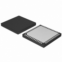
AMIS49587C5872RG ON Semiconductor, AMIS49587C5872RG Datasheet - Page 32

AMIS49587C5872RG
Manufacturer Part Number
AMIS49587C5872RG
Description
IC MODEM PLC 50/60MHZ 52QFN
Manufacturer
ON Semiconductor
Datasheet
1.AMIS49587C5871RG.pdf
(55 pages)
Specifications of AMIS49587C5872RG
Baud Rates
Selectable
Interface
SCI
Voltage - Supply
3 V ~ 3.6 V
Mounting Type
Surface Mount
Package / Case
52-TQFN Exposed Pad
Lead Free Status / RoHS Status
Lead free / RoHS Compliant
Data Format
-
Available stocks
Company
Part Number
Manufacturer
Quantity
Price
Company:
Part Number:
AMIS49587C5872RG
Manufacturer:
Seagate
Quantity:
1 000
MAINS_FREQ:
R_FS and R_FM step registers are defining the space and mark frequency. Explanation on the values can be found in paragraph
Sine wave generator. This register can be accessed via a WriteConfig_Request.
Table 31. FS AND FM STEP REGISTERS
difference between HIP_CLK, CIP_CLK and the – to + zero crossing of the mains. Explanation on the values can be found
in paragraph 50/60 Hz PLL. This register can be accessed via a WriteConfig_Request.
Table 32. ZC_ADJUST REGISTERS
TX output driver is fixed according to the value in R_ALC_CTRL[2:0]. Explanation on the attenuation values can be found
in paragraph Amplifier with Automatic Level Control. This register can be accessed via a WriteConfig_Request.
Table 33. ALC_CTRL REGISTERS
Where:
R_ALC_CTRL[3]:
R_ALC_CTRL[2:0]:
6.4.10 Reset and Low Power
ARM) excluding the data RAM for the ARM. This makes
sure that start- -up of hardware and ARM is guaranteed. A
Table 34. FIXED TRANSMITTER OUTPUT
ATTENUATION
R_ZC_ADJUST register defines the value which is pre- -loaded in the PLL counter. This is used to fine tune the phase
R_ALC_CTRL register enables or disables the Automatic Level Control. In case ALC is disabled the attenuation of the
AMIS- -49587 has 2 reset mode: hard reset and soft reset.
The hard reset initializes the complete IC (hardware and
R_ZC_ADJUST[7:0]
R_ALC_CTRL[3:0]
ALC_CTRL[2:0]
ARM Register
ARM Register
ARM Register
R_FM[15:0]
R_FS[15:0]
000
001
010
011
100
101
110
111
Hard Reset
Hard Reset
Hard Reset
0000h
0000h
11:
0:
1:
0:
1:
Fixed attenuation value
(See appendix C)
02h
00h
(See Table 41: Configuration Parameters)
Attenuation
--12 dB
--15 dB
--18 dB
--21 dB
--3 dB
--6 dB
--9 dB
0 dB
(See Table 41: Configuration Parameters)
Soft Reset
Soft Reset
Soft Reset
0000h
0000h
02h
00h
http://onsemi.com
48 data bits per mains period = 2400 baud @ 50 Hz
50 Hz
60 Hz
Automatic level control is enabled
Automatic level control is disabled and attenuation is fixed
32
Fine tuning of phase difference between CHIP_CLK and rising
hard reset is active when pin RESB = 0 or when the power
supply V
switching on the power supply the output of the crystal
oscillator is disable until a few 1000 clock pulses have been
detected, this to enable the oscillator to start up.
reset is activated when going into initialization mode for the
duration of maximum 1 CHIP_CLK. Initialization mode is
entered by R_CONF[5:3] = 000.
to have low power consumption. When working in transmit
mode the analogue receiver path and most of the digital
receive parts are disabled. When working in receive mode
the analog transmitter and most of the digital transmit parts,
except for the sine generation, are disabled.
minimal. Only a limited power is necessary to maintain the
bias of a minimum number of analog functions and the
oscillator cell.
The soft reset initializes part of the hardware. The soft
The concept of AMIS- -49587 has a number of provisions
When the pin RESB = 0 the power consumption is
Control register for the automatic level control
DD
Step register for the space frequency f
Step register for the mark frequency f
< V
edge of Mains zero crossing
POR
(See Table 14 Power On Reset). When
Description
Description
Description
M
S


