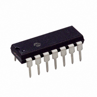
MCP2120-I/P Microchip Technology, MCP2120-I/P Datasheet - Page 11

MCP2120-I/P
Manufacturer Part Number
MCP2120-I/P
Description
IC ENCODER/DECODR INFRARED 14DIP
Manufacturer
Microchip Technology
Type
Infrared Encoder/Decoderr
Specifications of MCP2120-I/P
Package / Case
14-DIP (0.300", 7.62mm)
Voltage - Supply, Analog
2.5 V ~ 5.5 V
Voltage - Supply, Digital
2.5 V ~ 5.5 V
Mounting Type
Through Hole
Maximum Operating Temperature
+ 85 C
Minimum Operating Temperature
- 40 C
Mounting Style
Through Hole
Ic Function
Infrared Encoder/Decoder
Supply Voltage Range
2.5V To 5.5V
Operating Temperature Range
-40°C To +85°C
Digital Ic Case Style
DIP
No. Of Pins
14
Leaded Process Compatible
No
Rohs Compliant
Yes
Lead Free Status / RoHS Status
Lead free / RoHS Compliant
For Use With
MCP212XDM - BOARD DEVELOPMENT IRDA
Applications
-
Lead Free Status / Rohs Status
Lead free / RoHS Compliant
Available stocks
Company
Part Number
Manufacturer
Quantity
Price
Company:
Part Number:
MCP2120-I/P
Manufacturer:
ROHM
Quantity:
1 400
Part Number:
MCP2120-I/P
Manufacturer:
MICROCHIP/微芯
Quantity:
20 000
© 2009 Microchip Technology Inc.
The MCP2120/22 Developer’s Board, as shown in Figure 1-1, has the following
hardware features:
1. Mini USB connector (for powering the board).
2. Onboard +3.3V regulator for powering PIC18F65J50.
3. Hooks for an external regulated DC supply.
4. Jumper to issolate PIC18F65J50 power signal from the rest of board power. This
5. DB-9 connector and associated hardware for direct connection to MCP2120 or
6. Twelve-pin header connection to Host UART interface.
7. Four jumpers (3-pin) to select source of UART signals. Either DB-9 connector or
8. External Clock (from PIC18F65J50’s ECCP1 pin) Jumper.
9. Green power-on indicator LED.
10. Implemented IR transceiver circuit (two optional optical transceiver circuits
11. Reset switch for PIC18F65J50 device.
12. ICSP Header for PIC18F65J50.
13. Jumper option for PIC18F65J50 program selection (not installed).
14. PIC18F65J50 crystal.
15. MCP2120 crystal socket .
16. Jumper to select source of MCP2120/22 Reset signal.
17. Jumper to select source of MCP2120 MODE signal.
18. MCP2120/22 SOIC and DIP Footprints (DIP package is the default installation).
Note:
allows the board to operate at voltages higher than 3.3V.
MCP2122 UART (DB-9 interface requires RS-232 signal levels).
the PIC18F65J50.
implemented but not populated).
A schematic of the MCP2120/22 Developer’s Board is shown in
Section A.2 “Board - Schematic”
Product Overview
DS51842A-page 7


