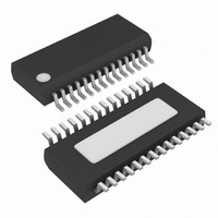
MAX9526AEI+ Maxim Integrated Products, MAX9526AEI+ Datasheet - Page 14

MAX9526AEI+
Manufacturer Part Number
MAX9526AEI+
Description
IC VID DECODER NTSC/PAL 28-QSOP
Manufacturer
Maxim Integrated Products
Type
Video Decoderr
Datasheet
1.MAX9526AEI.pdf
(38 pages)
Specifications of MAX9526AEI+
Applications
Automotive Systems, Players, TV
Voltage - Supply, Analog
1.8V
Voltage - Supply, Digital
1.8V
Mounting Type
Surface Mount
Package / Case
28-QSOP
Operating Supply Voltage
1.8 V
Maximum Operating Temperature
+ 125 C
Bandwidth
180 Hz to 2 KHz
Maximum Power Dissipation
1009 mW
Minimum Operating Temperature
- 40 C
Mounting Style
SMD/SMT
Snr
58.8 dB
Lead Free Status / RoHS Status
Lead free / RoHS Compliant
Low-Power, High-Performance
NTSC/PAL Video Decoder
Table 1. MAX9526 Clock Mode Summary
14
REGISTER 0x0D
______________________________________________________________________________________
_54MHz
SEL
B4
0
0
0
0
0
0
0
1
1
1
1
1
1
REGISTER 0x0D
XTAL_DIS
B3
X
0
0
0
1
1
1
0
1
1
1
1
1
REGISTER 0x0E
PLLBYP
B3
0
0
0
1
0
0
0
X
0
0
0
1
1
REGISTER 0x0E
LLC_MODE
B5-4
XX
XX
00
10
11
00
10
11
00
10
11
X0
11
Input clock = 27MHz crystal.
Sample clock = line locked or async (autodetected).
This is the default power-up mode for the MAX9526.
Input clock = 27MHz crystal.
Sample clock = line locked (forced on).
Input clock = 27MHz crystal.
Sample clock = 2x input clock.
Invalid modes. The PLL can only be bypassed if the
input clock is 54MHz.
Input clock = 27MHz external clock.
Sample clock = line locked or async (autodetected).
Input clock = 27MHz external clock.
Sample clock = line locked (forced on).
Input clock = 27MHz external clock.
Sample clock = 2x input clock.
Invalid mode. 54MHz crystal not supported.
Input clock = 54MHz external clock.
Sample clock = line locked or async (autodetected).
Input clock = 54MHz external clock.
Sample clock = line locked (forced on).
Input clock = 54MHz external clock.
Sample clock = input clock divided by 2, then
multiplied by 2x through the PLL. This mode uses the
PLL to filter high-frequency jitter on the input source.
Invalid mode. The PLL can only be bypassed when
the output is not a line-locked clock.
Input clock = 54MHz external clock.
Sample clock = input clock. Use this mode when a
low-jitter, 54MHz input clock is used.
CLOCK MODE DESCRIPTION


