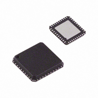
ADV7393BCPZ Analog Devices Inc, ADV7393BCPZ Datasheet - Page 66

ADV7393BCPZ
Manufacturer Part Number
ADV7393BCPZ
Description
IC DAC VIDEO HDTV 10BIT 40LFCSP
Manufacturer
Analog Devices Inc
Type
Video Encoderr
Datasheet
1.ADV7393BCPZ.pdf
(108 pages)
Specifications of ADV7393BCPZ
Design Resources
Reconstruction Video Filter Using ADA4430-1 Amplifier After ADV7393 Video Encoder (CN0101)
Applications
Set-Top Boxes, Video Players, Displays
Voltage - Supply, Analog
2.6 V ~ 3.46 V
Voltage - Supply, Digital
1.71 V ~ 1.89 V
Mounting Type
Surface Mount
Package / Case
40-LFCSP
Input Format
Digital
Output Format
Analog
Supply Voltage Range
1.71V To 1.89V
Operating Temperature Range
-40°C To +85°C
Tv / Video Case Style
LFCSP
No. Of Pins
40
Msl
MSL 1 - Unlimited
Lead Free Status / RoHS Status
Lead free / RoHS Compliant
For Use With
ADV7393-DBRDZ - BOARD EVAL FOR ADV7393EVAL-ADV7393EBZ - BOARD EVAL FOR ADV7393 ENCODER
Lead Free Status / RoHS Status
Lead free / RoHS Compliant, Lead free / RoHS Compliant
Available stocks
Company
Part Number
Manufacturer
Quantity
Price
Company:
Part Number:
ADV7393BCPZ
Manufacturer:
SIEMENS
Quantity:
101
Part Number:
ADV7393BCPZ
Manufacturer:
ADI/亚德诺
Quantity:
20 000
Company:
Part Number:
ADV7393BCPZ-3
Manufacturer:
ADI
Quantity:
302
Part Number:
ADV7393BCPZ-3
Manufacturer:
ADI/亚德诺
Quantity:
20 000
Company:
Part Number:
ADV7393BCPZ3
Manufacturer:
OSRAM
Quantity:
4 298
ADV7390/ADV7391/ADV7392/ADV7393
ED/HD Input
Sync Format
(Subaddress
0x30, Bit 2)
X
X
1
2
LOW POWER MODE
Subaddress 0x0D, Bits[2:0]
For power-sensitive applications, the ADV739x supports an
Analog Devices, Inc., proprietary low power mode of operation.
To use this low power mode, the DACs must be operating in
full-drive mode (R
not available in low-drive mode (R
Low power mode can be independently enabled or disabled on
each DAC using Subaddress 0x0D, Bits[2:0]. Low power mode
is disabled by default on all DACs.
In low-power mode, DAC current consumption is content
dependent and, on a typical video stream, it can be reduced by
as much as 40%. For applications requiring the highest possible
video performance, low power mode should be disabled.
CABLE DETECTION
Subaddress 0x10, Bits[1:0]
The ADV739x includes an Analog Devices proprietary cable
detection feature. The cable detection feature is available on
DAC 1 and DAC 2 when operating in full-drive mode (R
510 Ω, R
not available in low-drive mode (R
For a DAC to be monitored, the DAC must be powered up in
Subaddress 0x00.
The cable detection feature can be used with all SD, ED, and
HD video standards. It is available for all output configurations,
that is, CVBS, Y-C, YPrPb, and RGB output configurations.
For CVBS/Y-C output configurations, both DAC 1 and DAC 2
are monitored; that is, the CVBS and Y-C luma outputs are
monitored. For YPrPb and RGB output configurations, only
DAC 1 is monitored; that is, the luma or green output is
monitored.
Once per frame, the ADV739x monitors DAC 1 and/or DAC 2,
updating Subaddress 0x10, Bit 0 and/or Bit 1, respectively. If a
cable is detected on one of the DACs, the relevant bit is set to 0.
If not, the bit is set to 1.
In all ED/HD standards where there is a VSYNC output, the start of the VSYNC pulse is aligned with the falling edge of the embedded VSYNC in the output video.
X = don’t care.
L
= 37.5 Ω, assuming a connected cable). The feature is
SET
ED/HD VSYNC
Control
(Subaddress
0x34, Bit 2)
1
1
= 510 Ω, R
L
= 37.5 Ω). Low power mode is
SET
SET
ED/HD Sync
Output Enable
(Subaddress
0x02, Bit 7)
1
1
= 4.12 kΩ, R
= 4.12 kΩ, R
L
L
= 300 Ω).
= 300 Ω).
SD Sync
Output Enable
(Subaddress
0x02, Bit 6)
X
X
SET
=
Rev. B | Page 66 of 108
Video Standard
All ED/HD standards
except 525p
525p
DAC AUTOPOWER-DOWN
Subaddress 0x10, Bit 4
For power-sensitive applications, a DAC autopower-down
feature can be enabled using Subaddress 0x10, Bit 4. This
feature is available only when the cable detection feature is
enabled.
With this feature enabled, the cable detection circuitry monitors
DAC 1 and/or DAC 2 once per frame and, if they are
unconnected, automatically powers down some or all of the
DACs. Which DAC or DACs are powered down depends on the
selected output configuration. For CVBS/Y-C output configur-
ations, if DAC 1 is unconnected, only DAC 1 powers down. If
DAC 2 is unconnected, DAC 2 and DAC 3 power down.
For YPrPb and RGB output configurations, if DAC 1 is uncon-
nected, all three DACs are powered down. DAC 2 is not monitored
for YPrPb and RGB output configurations.
Once per frame, DAC 1 and/or DAC 2 is monitored. If a cable is
detected, the appropriate DAC or DACs remain powered up for
the duration of the frame. If no cable is detected, the appropriate
DAC or DACs power down until the next frame, when the
process is repeated.
SLEEP MODE
Subaddress 0x00, Bit 0
In sleep mode, most of the digital I/O pins of the ADV739x are
disabled. For inputs, this means that the external data is
ignored, and internally the logic normally driven by a given
input is just tied low or high. This includes CLKIN.
For digital output pins, this means that the pin goes into tristate
(high impedance) mode.
There are some exceptions to allow the user to continue to
communicate with the part via I
SCL pins are kept alive.
Most of the analogue circuitry is powered down when in sleep
mode. In addition, the cable detect feature no longer works as
the DACs are powered down.
Sleep mode is enabled using Subaddress 0x00, Bit 0.
Signal on VSYNC Pin
Pipelined ED/HD VSYNC
based on the vertical
counter
Pipelined ED/HD VSYNC
based on the vertical
counter
2
C: the RESET , ALSB, SDA and
Duration
Aligned with
serration lines.
Vertical blanking
interval.


