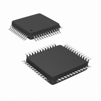
DP83848CVV/NOPB National Semiconductor, DP83848CVV/NOPB Datasheet - Page 18

DP83848CVV/NOPB
Manufacturer Part Number
DP83848CVV/NOPB
Description
IC TXRX ETHERNET PHYTER 48-LQFP
Manufacturer
National Semiconductor
Type
Transceiverr
Datasheet
1.DP83848CVVXNOPB.pdf
(84 pages)
Specifications of DP83848CVV/NOPB
Number Of Drivers/receivers
1/1
Protocol
Ethernet
Voltage - Supply
3 V ~ 3.6 V
Mounting Type
Surface Mount
Package / Case
48-LQFP
For Use With
DP83848C-POE-EK - BOARD EVALUATION DP83848CDP83848C-MAU-EK - BOARD EVALUATION DP83848C
Lead Free Status / RoHS Status
Lead free / RoHS Compliant
Other names
*DP83848CVV
*DP83848CVV/NOPB
DP83848CVV
DP83848CVVNOPB
DP83848CVVNOPB
DP83848CVVNOPBTR
DP83848CVVNOPBTR
*DP83848CVV/NOPB
DP83848CVV
DP83848CVVNOPB
DP83848CVVNOPB
DP83848CVVNOPBTR
DP83848CVVNOPBTR
Available stocks
Company
Part Number
Manufacturer
Quantity
Price
Company:
Part Number:
DP83848CVV/NOPB
Manufacturer:
TI
Quantity:
7 600
Company:
Part Number:
DP83848CVV/NOPB
Manufacturer:
NS
Quantity:
4 021
Company:
Part Number:
DP83848CVV/NOPB
Manufacturer:
Texas Instruments
Quantity:
10 000
Part Number:
DP83848CVV/NOPB
Manufacturer:
TI/德州仪器
Quantity:
20 000
www.national.com
2.3 PHY Address
The 5 PHY address inputs pins are shared with the
RXD[3:0] pins and COL pin as shown below.
The DP83848C can be set to respond to any of 32 possible
PHY addresses via strap pins. The information is latched
into the PHYCR register (address 19h, bits [4:0]) at device
power-up and hardware reset. The PHY Address pins are
shared with the RXD and COL pins. Each DP83848C or
port sharing an MDIO bus in a system must have a unique
physical address.
The DP83848C supports PHY Address strapping values 0
(<00000>) through 31 (<11111>). Strapping PHY Address
0 puts the part into Isolate Mode. It should also be noted
that selecting PHY Address 0 via an MDIO write to PHYCR
will not put the device in Isolate Mode. See Section 2.3.1for
more information.
For further detail relating to the latch-in timing requirements
of the PHY Address pins, as well as the other hardware
configuration pins, refer to the Reset summary in
Section 6.0.
Pin #
42
43
44
45
46
Table 2. PHY Address Mapping
PHYAD Function
PHYAD0
PHYAD1
PHYAD2
PHYAD3
PHYAD4
PHYAD4= 0
RXD Function
Figure 2. PHYAD Strapping Example
PHYAD3 = 0
RXD_0
RXD_1
RXD_2
RXD_3
COL
PHYAD2 = 0
18
Since the PHYAD[0] pin has weak internal pull-up resistor
and PHYAD[4:1] pins have weak internal pull-down resis-
tors, the default setting for the PHY address is 00001
(01h).
Refer to Figure 2 for an example of a PHYAD connection to
external components. In this example, the PHYAD strap-
ping results in address 00011 (03h).
2.3.1 MII Isolate Mode
The DP83848C can be put into MII Isolate mode by writing
to bit 10 of the BMCR register or by strapping in Physical
Address 0. It should be noted that selecting Physical
Address 0 via an MDIO write to PHYCR will not put the
device in the MII isolate mode.
When in the MII isolate mode, the DP83848C does not
respond to packet data present at TXD[3:0], TX_EN inputs
and presents a high impedance on the TX_CLK, RX_CLK,
RX_DV, RX_ER, RXD[3:0], COL, and CRS outputs. When
in Isolate mode, the DP83848C will continue to respond to
all management transactions.
While in Isolate mode, the PMD output pair will not transmit
packet data but will continue to source 100BASE-TX
scrambled idles or 10BASE-T normal link pulses.
The DP83848C can Auto-Negotiate or parallel detect to a
specific technology depending on the receive signal at the
PMD input pair. A valid link can be established for the
receiver even when the DP83848C is in Isolate mode.
PHYAD1 = 1
VCC
PHYAD0 = 1


