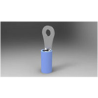
328996 TE Connectivity, 328996 Datasheet - Page 8

328996
Manufacturer Part Number
328996
Description
TERMINAL, PIDG R 16-14
Manufacturer
TE Connectivity
Type
One-Holer
Datasheet
1.31895.pdf
(14 pages)
Specifications of 328996
Angle
Straight
Brand/series
PIDG
Color
Blue
Contact Plating
Tin
Diameter, Insulation
0.17 "
Insulation Type
Nylon
Length, Overall
0.703 "
Material, Contact
Copper
Primary Type
Ring
Size, Stud
4
Termination
Wire
Width, Overall
0.25 "
Wire Size
16-14 AWG
Terminal Shape
Ring Tongue
Receptacle Style
Straight
Body Style
PIDG
Barrel Type
Closed Barrel
Wire/cable Type
Regular Wire
Insulation
Yes
Insulation Support
Insulation Support
Insulation Diameter (mm [in])
4.32 [.170] Max.
Stud Diameter (mm [in])
2.84 [0.112]
Stud Size
4
Shape
RING-041
Heavy Duty
No
Finish
Tin
Insulation Material
Nylon
Voltage (vac)
300
Wire/cable Size (cma)
2,050 – 5,180
Wire Range (mm [awg])
1.25-2.00² [16-14]
Tongue Material Thickness (mm [in])
0.84 [0.033]
Government/industry Qualification
No
Rohs/elv Compliance
RoHS compliant, ELV compliant
Lead Free Solder Processes
Not relevant for lead free process
Rohs/elv Compliance History
Always was RoHS compliant
Packaging Method
Loose Piece
Lead Free Status / Rohs Status
RoHS Compliant part
Crimped terminals, splices, or end caps should hold the wire conductor(s) firmly and have a pull–test tensile
value meeting that specified in the table in Figure 7.
of 14
If the wire insulation comes out during the bend test, the insulation crimp is not tight enough, and the
tooling must be adjusted to produce a tighter insulation crimp. Figure 8, Detail A shows a crimp that is too
loose, providing little or no support for the wire.
If the crimp passes the bend test, the insulation crimp must be tested by pulling the wire from the terminal,
splice, or end cap. If the wire insulation is only slightly deformed, the crimp is correct. Figure 8, Detail B
shows a desired crimp, providing adequate support without damage to either the insulation or the wire
conductor(s). If there is visible damage, such as tearing or piercing of the insulation, the crimp is too tight,
and the tooling must be adjusted to produce a looser insulation crimp. Figure 8, Detail C shows a crimp
that is too tight, damaging the insulation and possibly breaking wire conductor(s) or reducing circular mil
area (CMA) by wire extrusion.
Not to Scale
1. Using an unstripped wire, make a test crimp.
2. Hold the terminal, splice, or end cap in one hand. Use the side of one finger on the other hand at
approximately 76 [3] to push the wire up 90 _ and down 180 _ , one time each. Refer to Figure 6.
Adjust tensile testing machine for head travel of 25.4 [1.0] per minute. Directly and gradually apply force for 1 minute.
26
24
22
20
18
16
14
12
10
Hold Here
About 76.2 mm [3 in.]
(Test Crimp Using Unstripped Wire)
133.5 [30]
222.5 [50]
356.0 [80]
311.5 [70]
57.9 [13]
89.0 [20]
13.4 [3]
22.3 [5]
35.6 [8]
Bend Test
Figure 6
Figure 7
1st Push
90
667.2 [150]
489.3 [110]
169.0 [38]
222.5 [50]
311.5 [70]
44.5 [10]
66.7 [15]
84.5 [19]
2nd Push
31.1 [7]
180
Rev


