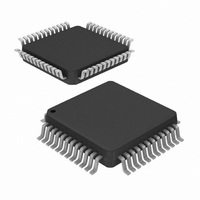
ISL5314INZ Intersil, ISL5314INZ Datasheet - Page 11

ISL5314INZ
Manufacturer Part Number
ISL5314INZ
Description
IC SYNTHESIZER DIGITAL 48-MQFP
Manufacturer
Intersil
Datasheet
1.ISL5314INZ.pdf
(17 pages)
Specifications of ISL5314INZ
Resolution (bits)
14 b
Master Fclk
125MHz
Tuning Word Width (bits)
48 b
Voltage - Supply
3 V ~ 5.5 V, 4.5 V ~ 5.5 V
Operating Temperature
-40°C ~ 85°C
Mounting Type
Surface Mount
Package / Case
48-LQFP
Supplier Package
LQFP
Resolution
14 Bit
Maximum Input Frequency
125(Min) MHz
Tuning Word Width
48 Bit
Minimum Operating Supply Voltage
4.5 V
Typical Operating Supply Voltage
5 V
Maximum Operating Supply Voltage
5.5 V
Minimum Operating Temperature
-40 °C
Maximum Operating Temperature
85 °C
Mounting
Surface Mount
Ic Function
Direct Digital Synthesizer
Supply Voltage Range
4.5V To 5.5V, 3V To 5.5V
Operating Temperature Range
-40°C To +85°C
Digital Ic Case Style
LQFP
No. Of Pins
48
Rohs Compliant
Yes
Lead Free Status / RoHS Status
Lead free / RoHS Compliant
Available stocks
Company
Part Number
Manufacturer
Quantity
Price
Company:
Part Number:
ISL5314INZ
Manufacturer:
PEREGRIN
Quantity:
2 800
Electrical Specifications
NOTES:
10. See “Definition of Specifications” on page 12.
12. For maximum value, 5.5V AV
13. For maximum value, 5.5V AV
11. 50MHz, High Z Load (~1MΩ), 15pF capacitance, (IN- = 0.5V
Input Resistance
Input Current
Maximum Input Voltage Allowed
Minimum Input Voltage, Peak-to-Peak (Dependent on Noise)
Propagation Delay, High to Low
Propagation Delay, Low to High
Output Rise Time
Output Fall Time
Output High Voltage, V
Output Low Voltage, V
Output Jitter
Maximum Output Toggle Rate
POWER SUPPLY CHARACTERISTICS
AV
DV
Analog Supply Current (I
Digital Supply Current (I
Power Dissipation
Power Supply Rejection
4. Parameters with MIN and/or MAX limits are 100% tested at +25°C, unless otherwise specified. Temperature limits established by characterization
5. Gain error for the DAC is measured as the error in the ratio between the full scale output current and the current through R
6. Limits established by characterization and are not production tested.
7. Spectral measurements made with differential transformer coupled output and no external filtering.
8. Measured with the clock at 125MSPS and the output frequency at 10MHz.
9. Measured with the clock at 100MSPS and the output frequency at 10MHz.
DD
DD
and are not production tested.
ideally the ratio should be 32.
(Analog) Power Supply
(Digital) Power Supply
PARAMETER
OL
OH
DVDD
AVDD
)
)
DD
DD
11
AV
all Min and Max Values. T
temperature range, -40°C to +85°C. (Continued)
and 3.6V DV
and 5.5V DV
DD
(Excluding Comparator Sleep Mode)
(Note 11)
(Note 11)
(Note 11)
(Note 11)
I
I
High Z Load (~1MΩ)
5V, I
5V, I
5V (Notes 8, 13)
3.3V (Notes 9, 12)
AV
AV
Single 5V Supply (Note 10)
OH
OL
= DV
DD
DD
= +4mA
= -4mA
OUTFS
OUTFS
DD
= 5V, DV
= 5V, DV
DD
DD
= +5V (unless otherwise noted), V
= 20mA (Note 13)
= 2mA
are used.
are used.
DD
DD
= 3.3V, I
= 5V, I
A
TEST CONDITIONS
= +25°C for All Typical Values. Boldface limits apply over the operating
P-P
OUTFS
ISL5314
OUTFS
), (IN+ = 0.25V
= 20mA (Notes 8, 13)
= 20mA (Notes 9, 12)
DC
REF
).
= Internal 1.2V, IOUTFS = 20mA, T
(Note 4)
MIN
-0.2
2.6
4.5
3.0
-
-
-
-
-
-
-
-
-
-
-
-
-
-
-
-
-
TYP
100
290
625
4.0
0.1
1.5
1.3
0.5
5.0
3.3
>1
25
90
50
1
6
5
7
-
-
-
A
SET
= -40°C to +85°C for
(Note 4)
MAX
3.75
+0.2
100
363
715
0.4
5.5
5.5
(typically 625µA);
30
55
-
-
-
-
-
-
-
-
-
-
-
January 19, 2010
% FSR/V
UNITS
FN4901.3
V
MHz
mW
mW
MΩ
mA
mA
mA
mA
μA
ns
ns
ns
ns
ns
P-P
V
V
V
V
V


