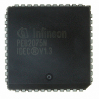
PEB2075N-V13TR Infineon Technologies, PEB2075N-V13TR Datasheet - Page 20

PEB2075N-V13TR
Manufacturer Part Number
PEB2075N-V13TR
Description
IC CONTROLLER D-CH EXCH 44-PLCC
Manufacturer
Infineon Technologies
Datasheet
1.PEB2075N-V13TR.pdf
(81 pages)
Specifications of PEB2075N-V13TR
Controller Type
Digital Exchange Controller
Interface
PCM
Voltage - Supply
4.75 V ~ 5.25 V
Current - Supply
10mA
Operating Temperature
0°C ~ 70°C
Mounting Type
Surface Mount
Package / Case
44-PLCC
Lead Free Status / RoHS Status
Contains lead / RoHS non-compliant
Other names
PEB2075N-V13INTR
PEB2075N-V13TR
PEB2075N-V13TR
Available stocks
Company
Part Number
Manufacturer
Quantity
Price
Company:
Part Number:
PEB2075N-V13TR
Manufacturer:
LT
Quantity:
512
Company:
Part Number:
PEB2075N-V13TR
Manufacturer:
Infineon Technologies
Quantity:
10 000
2.3
Microcontroller Interface
The IDEC is programmable over an 8-bit parallel microcontroller interface. Easy and fast
microprocessor access is provided by 8-bit address decoding on chip. The interface consists of 13
(19) lines and is directly compatible with processors of the multiplexed and demultiplexed address/
data bus types (Siemens/Intel or Motorola processor families). The microprocessor interface
signals are summarized in table 2.
Table 2
Microcontroller Interface Signals of the IDEC
Symbol
AD0
AD1
AD2
AD3
AD4
AD5
AD6
AD7
A0 ... A6
CS
WR
R/W
RD
DS
Semiconductor Group
Interfaces
Input (I)
Output (O)
Open Drain
(OD)
I/O
I
I
I
I
Function
Address Data Bus. If the multiplexed address/data P interface
bus mode is selected these lines transfer data and commands
between the P and the IDEC.
If a demultiplexed mode is used, these lines interface with the
system data bus.
Address Bus. These inputs interface to the system´s address
bus to select an internal register for a read or write access. Only
provided in the P-LCC package and only active if a
demultiplexed P interface is selected.
Chip Select. A low on this line selects the IDEC for a read/write
operation.
Write. This signal indicates a write operation, active low
(Siemens/Intel bus mode).
Read/Write. At "high", identifies a valid P access as a read
operation. At "low", identifies a P access as a write operation
(Motorola bus mode). Only provided in the P-LCC package.
Read. This signal indicates a read operation, active low
(Siemens/Intel bus mode).
Data Strobe. The rising edge marks the end of a valid read or
write operation (Motorola bus mode). Only provided in the
P-LCC package.
20
Functional Description


