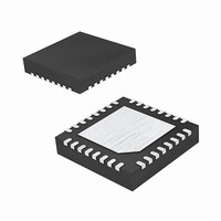
IDT92HD75B2X3NLGXYAX IDT, Integrated Device Technology Inc, IDT92HD75B2X3NLGXYAX Datasheet - Page 19

IDT92HD75B2X3NLGXYAX
Manufacturer Part Number
IDT92HD75B2X3NLGXYAX
Description
IC AUDIO CODEC HD 4CH 32-VFQFPN
Manufacturer
IDT, Integrated Device Technology Inc
Type
Audio Codec, HDr
Datasheet
1.IDT92HD75B1X3NLGXYAX8.pdf
(214 pages)
Specifications of IDT92HD75B2X3NLGXYAX
Resolution (bits)
24 b
Number Of Adcs / Dacs
2 / 2
Sigma Delta
No
S/n Ratio, Adcs / Dacs (db) Typ
86 / 95
Dynamic Range, Adcs / Dacs (db) Typ
86 / 93
Voltage - Supply, Analog
3.14 V ~ 3.47 V; 3.8 V ~ 4.2 V; 4.28 V ~ 4.73 V; 4.75 V ~ 5.25 V
Voltage - Supply, Digital
3.14 V ~ 3.47 V
Operating Temperature
0°C ~ 70°C
Mounting Type
Surface Mount
Package / Case
32-VFQFN, 32-VFQFPN
Lead Free Status / RoHS Status
Lead free / RoHS Compliant
Other names
92HD75B2X3NLGXYAX
- Current page: 19 of 214
- Download datasheet (3Mb)
4-CHANNEL HD AUDIO CODECS OPTIMIZED FOR LOW POWER
0
1
2
3
4
Power State
D0
D1
D2
D3
D0-D3
92HD75B
4-CHANNEL HD AUDIO CODECS OPTIMIZED FOR LOW POWER
Digital Mics
Yes
Yes
Yes
Yes
No
DMIC Widget
N/A
Single Edge
Double Edge on
either DMIC_0 or 1
OR
Single Edge on
DMIC_0 and 1
Double Edge on
one DMIC pin and
Single Edge on the
second DMIC pin.
Double Edge
Enabled?
Data Sample
Clock Capable
Clock Disabled
Clock Disabled
Clock Disabled
Clock Disabled
Table 8. DMIC_CLK and DMIC_0,1 Operation During Power States
DMIC_CLK
Output
N/A
0, or 1
0, or 1
0, or 1
0, or 1
ADC Conn.
Table 7. Valid Digital Mic Configurations
Input Capable
Input Disabled
Input Disabled
Input Disabled
Input Disabled
DMIC_0,1
No Digital Microphones
Available on either DMIC_0 or DMIC_1
Both ADC Channels produce data, may be in phase or out by 1/2 DMIC_CLK
period depending upon external configuration and timing
Available on either DMIC_0 or DMIC_1, External logic required to support
sampling on a single Digital Mic pin channel on rising edge and second Digital Mic
right channel on falling edge of DMIC_CLK for those digital microphones that don’t
support alternative clock edge capability. If both DMIC_0 and DMIC_1 are used to
support 2 digital microphones, 2 separate ADC units will be used, however, this
configuration is not recommended since it consumes two stereo ADC resources.
Requires both DMIC_0 AND DMIC_1, External logic required to support sampling
on a single Digital Mic pin channel on rising edge and second Digital Mic right
channel on falling edge of DMIC_CLK for those digital microphones that don’t
support alternative clock edge capability. Two ADC units are required to support
this configuration
Connected to DMIC_0 and DMIC_1, External logic required to support sampling
on a single Digital Mic pin channel on rising edge and second Digital Mic right
channel on falling edge of DMIC_CLK for those digital microphones that don’t
support alternative clock edge capability. Two ADC units are required to support
this configuration
19
DMIC_CLK Output is Enabled when either DMIC_0 or DMIC_1
Input Widget is Enabled. Otherwise, the DMIC_CLK remains Low
DMIC_CLK Output is Enabled when either DMIC_0 or DMIC_1
Input Widget is Enabled. Otherwise, the DMIC_CLK remains Low
DMIC_CLK Remains Low
DMIC_CLK Remains Low
DMIC_CLK is HIGH-Z with Weak Pull-down
Notes
92HD75B
Notes
PC AUDIO
V 1.0 01-09
Related parts for IDT92HD75B2X3NLGXYAX
Image
Part Number
Description
Manufacturer
Datasheet
Request
R

Part Number:
Description:
TRANSLATION DEVICE DPI 80-PQFP
Manufacturer:
IDT, Integrated Device Technology Inc
Datasheet:

Part Number:
Description:
IDT PART
Manufacturer:
IDT, Integrated Device Technology Inc
Datasheet:

Part Number:
Description:
IC LIU T1/E1/J1 OCTAL 256PBGA
Manufacturer:
IDT, Integrated Device Technology Inc
Datasheet:

Part Number:
Description:
IC FREQ TIMING GENERATOR 28TSSOP
Manufacturer:
IDT, Integrated Device Technology Inc
Datasheet:

Part Number:
Description:
IC CLK DVR PLL 1:10 40VFQFPN
Manufacturer:
IDT, Integrated Device Technology Inc
Datasheet:

Part Number:
Description:
IC CLK FANOUT BUFFER 1:18 32LQFP
Manufacturer:
IDT, Integrated Device Technology Inc
Datasheet:

Part Number:
Description:
IC CLK FANOUT BUFFER 1:18 32LQFP
Manufacturer:
IDT, Integrated Device Technology Inc
Datasheet:

Part Number:
Description:
IC CK505 VREG/RES 56TSSOP
Manufacturer:
IDT, Integrated Device Technology Inc
Datasheet:

Part Number:
Description:
IC SDRAM CLK DVR 1:10 48-TSSOP
Manufacturer:
IDT, Integrated Device Technology Inc
Datasheet:

Part Number:
Description:
IC CLK DVR PLL 1:10 48TSSOP
Manufacturer:
IDT, Integrated Device Technology Inc
Datasheet:

Part Number:
Description:
IC FLEXPC CLK PROGR P4 56-TSSOP
Manufacturer:
IDT, Integrated Device Technology Inc
Datasheet:

Part Number:
Description:
IC FLEXPC CLK PROGR P4 56-TSSOP
Manufacturer:
IDT, Integrated Device Technology Inc
Datasheet:

Part Number:
Description:
IC FLEXPC CLK PROGR P4 56-SSOP
Manufacturer:
IDT, Integrated Device Technology Inc
Datasheet:

Part Number:
Description:
IC PLL CLK DRIVER 2.5V 28-TSSOP
Manufacturer:
IDT, Integrated Device Technology Inc
Datasheet:

Part Number:
Description:
IC CLOCK DRIVER 2.5V 24-TSSOP
Manufacturer:
IDT, Integrated Device Technology Inc
Datasheet:


