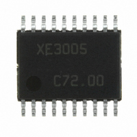
XE3005I033TRLF Semtech, XE3005I033TRLF Datasheet - Page 8

XE3005I033TRLF
Manufacturer Part Number
XE3005I033TRLF
Description
IC CODEC LOW PWR 16BIT 20-TSSOP
Manufacturer
Semtech
Type
Audio Codecr
Datasheet
1.XE3005I064TRLF.pdf
(37 pages)
Specifications of XE3005I033TRLF
Data Interface
Serial
Resolution (bits)
16 b
Number Of Adcs / Dacs
1 / 1
Sigma Delta
Yes
S/n Ratio, Adcs / Dacs (db) Typ
78 / 78
Dynamic Range, Adcs / Dacs (db) Typ
78 / 78
Voltage - Supply, Analog
1.8 V ~ 3.6 V
Voltage - Supply, Digital
1.8 V ~ 3.6 V
Operating Temperature
-20°C ~ 70°C
Mounting Type
Surface Mount
Package / Case
20-TSSOP
Lead Free Status / RoHS Status
Lead free / RoHS Compliant
Other names
XE3005I033TR
2.1.4
In digital loop back mode, the ADC output is routed directly to the DAC input. This allows in-circuit system level tests. The
digital loop back mode can be selected through register J.
2.1.5
A master clock (MCLK) has to be applied to the XE3005/3006. The clock frequency of the signal applied to the MCLK pin
may vary between 1.024 MHz minimum and 33.9 MHz maximum. The maximum internal clock signal frequency
(MCLK/div_factor) should not exceed 12.288 MHz.
The div_factor can be set by the user in register I to 1,2 or 4. The default value for div_factor is ‘1’.
2.1.6
The Serial Audio Interface is a 4-wire interface for bi-directional communication of audio data. It operates on the bit serial
clock BCLK and the frame synchronization signal FSYNC. The sampling frequency of the CODEC corresponds to the
rate at which the Audio Serial Interface will put out succeeding frames. One frame always corresponds to one sample.
One frame always contains 2 channels.
Synchronizing the Serial Audio Interface to the MCLK is recommended. FSYNC and MCLK must have a fixed ratio as
defined by the following relation:
FSYNC = Sampling frequency = frame rate = MCLK/(256 x div_factor).
The pin BCLK defines the time when the data must be presented to the serial audio interface and shifted into (pin SDI) or
out of (pin SDO) the CODEC. The number of BCLK periods in one FSYNC period is 32. The user can select to use the
first 16 clock cycles (channel 1) or the second 16 clock cycles (channel 2) of BLCK to shift in or out the data samples.
The table below shows some examples of the relationships between MCLK, BCLK and FSYNC
The table below shows the possible functional configurations of the serial audio interface
By default the Serial Audio Interface operates in slave, SFS mode. In slave mode the user needs to generate the signals
BLCK, FSYNC and supply to the CODEC.
In master mode the CODEC generates the BLCK and FSYNC signals. In that case the BLCK operates at 32 times the
frequency of FSYNC. The CODEC master mode can be used with the LFS protocol only.
The register J is used for the different setups of the serial audio interface.
© Semtech 2005
22579.2 kHz
Digital Loop Back
Operating Frequency
Serial Audio Interface
2048 kHz
8192 kHz
5120 kHz
MCLK
CODEC
master
slave
Div_factor
supported protocol
LFS (Long Frame Sync)
LFS, LFS Optimization and SFS (Short Frame Sync)
1
4
1
2
8
1411.2 kHz
256 kHz
256 kHz
640 kHz
BCLK
XE3005/XE3006
44.1 kHz
FSYNC
20 kHz
8 kHz
8 kHz
www.semtech.com


