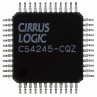
CS4245-CQZ Cirrus Logic Inc, CS4245-CQZ Datasheet - Page 42

CS4245-CQZ
Manufacturer Part Number
CS4245-CQZ
Description
IC CODEC AUD STER 104DB 48LQFP
Manufacturer
Cirrus Logic Inc
Type
Stereo Audior
Datasheet
1.CS4245-CQZ.pdf
(57 pages)
Specifications of CS4245-CQZ
Package / Case
48-LQFP
Data Interface
Serial
Resolution (bits)
24 b
Number Of Adcs / Dacs
2 / 2
Sigma Delta
Yes
Dynamic Range, Adcs / Dacs (db) Typ
104 / 104
Voltage - Supply, Analog
3.13 V ~ 5.25 V
Voltage - Supply, Digital
3.13 V ~ 5.25 V
Operating Temperature
-10°C ~ 70°C
Mounting Type
Surface Mount
Number Of Adc Inputs
12
Number Of Dac Outputs
4
Conversion Rate
192 KSPS
Interface Type
Serial (I2C, SPI)
Resolution
24 bit
Operating Supply Voltage
3.3 V, 5 V
Maximum Operating Temperature
+ 70 C
Mounting Style
SMD/SMT
Minimum Operating Temperature
- 10 C
Number Of Channels
2 ADC/2 DAC
Thd Plus Noise
- 95 dB ADC / - 90 dB DAC
Lead Free Status / RoHS Status
Lead free / RoHS Compliant
For Use With
598-1501 - BOARD EVAL FOR CS4245 CODEC
Lead Free Status / Rohs Status
Lead free / RoHS Compliant
Other names
598-1034
Available stocks
Company
Part Number
Manufacturer
Quantity
Price
Company:
Part Number:
CS4245-CQZ
Manufacturer:
CIRRUS
Quantity:
455
Part Number:
CS4245-CQZ
Manufacturer:
CIRRUS
Quantity:
20 000
Company:
Part Number:
CS4245-CQZR
Manufacturer:
Schneider
Quantity:
1 000
Company:
Part Number:
CS4245-CQZR
Manufacturer:
Cirrus Logic Inc
Quantity:
10 000
42
6.2.4
6.2.5
6.3
6.3.1
6.3.2
6.3.3
DAC_FM1
7
DAC Control - Address 03h
Power-Down DAC (Bit 1)
Function:
The DAC pair will remain in a reset state whenever this bit is set.
Power-Down Device (Bit 0)
Function:
The device will enter a low-power state whenever this bit is set. The power-down bit is set by default and
must be cleared before normal operation can occur. The contents of the control registers are retained
when the device is in power-down.
DAC Functional Mode (Bits 7:6)
Function:
Selects the required range of input sample rates.
DAC Digital Interface Format (Bits 5:4)
Function:
The required relationship between LRCK, SCLK and SDIN for the DAC is defined by the DAC Digital In-
terface Format and the options are detailed in
Mute DAC (Bit 2)
Function:
The DAC outputs will mute and the MUTEC pin will become active when this bit is set. Though this bit is
active high, it should be noted that the MUTEC pin is active low. The common mode voltage on the outputs
will be retained when this bit is set. The muting function is effected, similar to attenuation changes, by the
DACSoft and DACZero bits in the DAC Control 2 register.
DAC_DIF1 DAC_DIF0
DAC_FM1
0
0
1
1
0
0
1
1
DAC_FM0
6
DAC_FM0
0
1
0
1
0
1
0
1
DAC_DIF1
5
Left Justified, up to 24-bit data (default)
Single-Speed Mode: 4 to 50 kHz sample rates
Double-Speed Mode: 50 to 100 kHz sample rates
Quad-Speed Mode: 100 to 200 kHz sample rates
Reserved
Table 7. DAC Digital Interface Formats
Table 6. Functional Mode Selection
Right-Justified, 16-bit Data
Right-Justified, 24-bit Data
DAC_DIF0
I²S, up to 24-bit data
Description
4
Table 7
Reserved
3
and
Mode
Figures
MuteDAC
7-9.
2
Format
0
1
2
3
DeEmph
1
Figure
7
8
9
9
DAC_M/S
CS4245
DS656F2
0


