1CPSC2 Honeywell, 1CPSC2 Datasheet

Control Switches SAFETY

1CPSC2

Manufacturer Part Number
1CPSC2
Description
Control Switches SAFETY
Manufacturer
Honeywell
Datasheet

Specifications of 1CPSC2

Control Type
Cable Pull Safety Switch
Contact Form
2 NC / 2 NO
Contact Rating
50 mAmps to 10 Amps
Flange Shape
Rectangular
Illuminated
Y
Description/function
Provides readily accessible emergency stop signal
Illumination
Illuminated
CPS Series
Cable Pull Safety Switch
FEATURES
• Direct opening action
• 2CPS: 2NO/2NC, 1NO/3NC or 4NC
• Typical cable span of 76 m (250 ft) in an
• Choice of three actuator configurations
• Removable contact block version
• Large wiring cavity with straight-
• 24 Vdc or 120 Vac bright, multicluster
• Gold-plated contacts are standard on
• Die-cast zinc housing
• Optional hardware packs available
TYPICAL APPLICATIONS
• Long conveyor systems found in
• Conveyor systems having a high amount
• Conveyor systems that experience wide
• Long conveyor systems where easy
• Hose down conditions
• Packaging equipment
• Assembly lines
© Honeywell International Inc. - April 2003
(normally closed) contacts
contact configurations
1CPS: 1NO/1NC, 2NO/2NC, 1NO/3NC or
4NC contact configurations
environment with a temperature change
of ±17 °C (±30 °F). Longer spans are
possible depending upon temperature
change and installation
(ref. note on page 6 for more details or
Application note - Effect of Temperature
on Cable Pull Switch Operation)
(2CPS)
available (2CPS)
through wiring
LED status indicator light available on
2CPS. Single high intensity LED on 1CPS
2CPS, available on 1CPS
warehouses and distribution centers
of vibration
temperature swings
through wiring, or highly visible trip
status is required
of NC
• Safety Products for Machine Safeguarding •
(Applied for)
CPS Series Cable Pull Safety Switches provide a readily accessible emergency stop
signal. This is a cost-effective means compared to using multiple emergency stop
push-buttons. (Cable Pull Safety Switches are not, however, to be used as a means
of personnel safeguarding. They may be used to prevent further injury or damage to
equipment when used for emergency stop signaling.)
The CPS Series Cable Pull Safety switch is designed to provide emergency stop
protection for exposed conveyor and assembly lines. The internal mechanism
latches on both slackened cable (push) and pulled cable. This capability also en-
hances productivity by eliminating nuisance stops due to variations in temperature,
stretch of cable over time, and other application variables.
The 1CPS is intended for use in applications where the cable span is 76 m (250 ft)
or shorter. It is an economical solution for shorter runs or zone protection typical to
automated systems. The 2CPS series is intended for use in very long cable runs of
152 m (500 ft) or shorter, such as long conveyor lines found in warehouses.
A line in the midpoint of the cable tension window indicates proper cable tension,
providing easy set-up. The direct opening switch contacts are held closed when the
actuating cable is under proper tension and the reset knob is set to RUN. When the
actuating cable is pulled, slackened or broken, a cam positively opens the NC (Nor-
mally Closed) switch contacts. The snap action, trip operation causes the switch
contacts to change state and mechanically latch almost simultaneously when the
cable is pulled, slackened or broken. The NC switch contacts remain open until the
CPS is reset by properly tensioning the cable and manually rotating the reset knob.
When the direct opening switch contacts open, the auxiliary contacts also actuate
(open contacts close and closed contacts open). The auxiliary contacts are electri-
cally isolated from the direct opening switch contacts. These NO (Normally Open)
contacts may be used for monitoring or signaling.
The CPS complies with: Low Voltage Directive 73/23/EEC, as amended by directive
93/68/EEC; Machinery Directive 98/37/EEC only as the directives relate to the
components being used in a safety function; IEC/EN 60947-1; IEC/EN 60947-5-1;
IEC/EN 60947-5-5.
BG
MISUSE OF DOCUMENTATION
• The information presented in this product sheet (or catalogue) is for reference only. DO NOT USE this document as system
• Complete installation, operation and maintenance information is provided in the instructions supplied with each product.
Failure to comply with these instructions could result in death or serious injury.
!
installation information.
WARNING
1

Related parts for 1CPSC2

1CPSC2 Summary of contents

Page 1

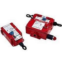
... Hose down conditions • Packaging equipment • Assembly lines © Honeywell International Inc. - April 2003 BG (Applied for) CPS Series Cable Pull Safety Switches provide a readily accessible emergency stop signal. This is a cost-effective means compared to using multiple emergency stop push-buttons ...

Page 2

... Safety Products for Machine Safeguarding • 2 NORMALLY CLOSED/ 2 NORMALLY OPEN *9 (0.39) *9,9 12,7 7,9 3,8 3,8 7,9 (0.39) (0.50) (0.31) (0.15) (0.15) (0.31) 12,7 (0.50) 21-22 A 13-14 21-22 B 13- #6-32 UNC © Honeywell International Inc. - April 2003 22 14 *9,9 (0.39) 12,7 (0.50) E ...

Page 3

... A 13-14 11-12 B 21- #6-32 UNC © Honeywell International Inc. - April 2003 4 NORMALLY CLOSED *9,9 *9 (0.39) (0.39) 12,7 7,9 3,8 3,8 7,9 12,7 (0.50) (0.31) (0.15) (0.15) (0.31) (0.50) 11-12 A ...

Page 4

... Safety Products for Machine Safeguarding • 3 NORMALLY CLOSED/ 1 NORMALLY OPEN *9,9 *9 (0.39) (0.39) 3,8 7,9 12,7 12,7 7,9 3,8 (0.15) (0.31) (0.50) (0.50) (0.31) (0.15) 21-22 A 13-14 11-12 B 21- © Honeywell International Inc. - April 2003 *9 (0.39) 3,8 7,9 12,7 (0.15) (0.31) (0.50 ...

Page 5

... A 21-22 11-12 B 21- Removable contact blocks with heavy duty wiring receptacles © Honeywell International Inc. - April 2003 Actuation Code 1: Maintained both sides 1 2: Maintained left side actuation right side 3: Maintained right side actuation left side #6-32 UNC • Safety Products for Machine Safeguarding • ...

Page 6

... D = Cable Pull Switch usable temperature span with endspring or second CPS E = Cable span distance 45,7 m 68,8 m 76,2 m 137,2 m 114,3 m [150 ft] [225 ft] [250 ft] [375 ft] [450 ft] E • Safety Products for Machine Safeguarding • 160,0 m 182,9 m 205,7 m 228,6 m [525 ft] [600 ft] [675 ft] [750 ft] © Honeywell International Inc. - April 2003 ...

Page 7

... B 2 ft] maximum [250 ft] typical D Reset knob 2CPS [18 in] maximum B 2 ft] maximum [250 ft] typical D J-hook turnbuckle (included) E Thimble F Cable clamp © Honeywell International Inc. - April 2003 Tension indicator line is in center of indicator window – cable is properly tensioned F J-hook turnbuckle G Thimble RUN ...

Page 8

... Mounting bracket (to be used with 1CPS or 2CPS) J-hook turnbuckle with lock nuts (included with 2CPS) 71,88 ±2,54 11,43 [2.83 ±0.10] [0.45 207,01 ±1,27 [8.15 ±0.05] • Safety Products for Machine Safeguarding • D 227,33 ±12,7 [8.95 ±0.50] © Honeywell International Inc. - April 2003 ...

Page 9

... A (12.75) 21,1 (0.75) 34,9 (1.38) 152,4 (6.00) 104,8 (4.13) 6,4 (0.25) 12,7 (0.50) © Honeywell International Inc. - April 2003 152,4 [6.0] 81,28 [3.2] 4X Ø 7,11 Ø 0.28 50,8 117,42 [2.1] [4.623 79,8 (3.14) 152,4 (6.00) 52,1 (2.05) 12,7 (0 ...

Page 10

... Phone: +(359 FAX: +(359 This publication does not constitute a contract between Honeywell and its customers. The contents may be changed at any time without notice the customer's responsibility to ensure safe installation and operation of the products. Detailed mounting drawings of all products illustrated are available on request. © ...

Related keywords