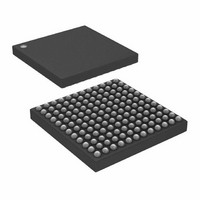
ADSP-2184NKCA-320 Analog Devices Inc, ADSP-2184NKCA-320 Datasheet - Page 21

ADSP-2184NKCA-320
Manufacturer Part Number
ADSP-2184NKCA-320
Description
IC DSP 16BIT 80MHZ 144CSPBGA
Manufacturer
Analog Devices Inc
Series
ADSP-21xxr
Type
Fixed Pointr
Datasheet
1.ADSP-2185NKSTZ-320.pdf
(48 pages)
Specifications of ADSP-2184NKCA-320
Rohs Status
RoHS non-compliant
Interface
Host Interface, Serial Port
Clock Rate
80MHz
Non-volatile Memory
External
On-chip Ram
20kB
Voltage - I/o
3.30V
Voltage - Core
1.80V
Operating Temperature
0°C ~ 70°C
Mounting Type
Surface Mount
Package / Case
144-CSPBGA
Device Core Size
16b
Architecture
Enhanced Harvard
Format
Fixed Point
Clock Freq (max)
80MHz
Mips
80
Device Input Clock Speed
80MHz
Ram Size
20KB
Program Memory Size
Not RequiredKB
Operating Supply Voltage (typ)
1.8/2.5/3.3V
Operating Supply Voltage (min)
1.71V
Operating Supply Voltage (max)
1.89/3.6V
Operating Temp Range
0C to 70C
Operating Temperature Classification
Commercial
Mounting
Surface Mount
Pin Count
144
Package Type
CSPBGA
Package
144CSP-BGA
Numeric And Arithmetic Format
Fixed-Point
Maximum Speed
80 MHz
Device Million Instructions Per Second
80 MIPS
Lead Free Status / Rohs Status
Not Compliant
Available stocks
Company
Part Number
Manufacturer
Quantity
Price
Company:
Part Number:
ADSP-2184NKCA-320
Manufacturer:
Analog Devices Inc
Quantity:
10 000
Table 12. Unused Pin Terminations (Continued)
1
2
3
4
5
Pin Name
ERESET
EMS
EINT
ECLK
ELIN
ELOUT
CLKIN, RESET, and PF3–0/Mode D–A are not included in this table because these pins must be used.
All bidirectional pins have three-stated outputs. When the pin is configured as an output, the output is Hi-Z (high impedance) when inactive.
Hi-Z = High Impedance.
If the CLKOUT pin is not used, turn it OFF, using CLKODIS in SPORT0 autobuffer control register.
If the Interrupt/Programmable Flag pins are not used, there are two options: Option 1: When these pins are configured as INPUTS at reset and function as interrupts
and input flag pins, pull the pins High (inactive). Option 2: Program the unused pins as OUTPUTS, set them to 1 prior to enabling interrupts, and let pins float.
1
I/O
3-State
(Z)
I
O
I
I
I
O
2
Reset
State
I
O
I
I
I
O
Rev. A | Page 21 of 48 | August 2006
Hi-Z
3
Caused By
Unused Configuration
Float
Float
Float
Float
Float
Float
ADSP-218xN


