DSP56303AG100 Freescale Semiconductor, DSP56303AG100 Datasheet - Page 22
DSP56303AG100
Manufacturer Part Number
DSP56303AG100
Description
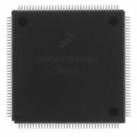
IC DSP 24BIT 100MHZ 144-LQFP
Manufacturer
Freescale Semiconductor
Series
DSP563xxr
Type
Fixed Pointr
Datasheet
1.DSP56303AG100.pdf
(108 pages)
Specifications of DSP56303AG100
Interface
Host Interface, SSI, SCI
Clock Rate
100MHz
Non-volatile Memory
ROM (576 B)
On-chip Ram
24kB
Voltage - I/o
3.30V
Voltage - Core
3.30V
Operating Temperature
-40°C ~ 100°C
Mounting Type
Surface Mount
Package / Case
144-LQFP
Package
144LQFP
Maximum Speed
100 MHz
Ram Size
24 KB
Device Million Instructions Per Second
100 MIPS
Lead Free Status / RoHS Status
Lead free / RoHS Compliant
Available stocks
Company
Part Number
Manufacturer
Quantity
Price
Company:

Part Number:
DSP56303AG100
Manufacturer:
Freescale Semiconductor
Quantity:
10 000
Company:
Part Number:
DSP56303AG100B1
Manufacturer:
Freescale Semiconductor
Quantity:
10 000
Company:
Part Number:
DSP56303AG100R2
Manufacturer:
Freescale Semiconductor
Quantity:
10 000


Specifications
2.3 Thermal Characteristics
2.4 DC Electrical Characteristics
2-2
Junction-to-ambient thermal resistance
Junction-to-case thermal resistance
Thermal characterization parameter
Notes:
Supply voltage
Input high voltage
•
•
•
Input low voltage
•
•
•
Input leakage current
High impedance (off-state) input current (@ 2.4 V / 0.4 V)
Output high voltage
•
•
Output low voltage
•
•
Internal supply current
•
•
•
PLL supply current
Input capacitance
D[0–23], BG, BB, TA
MOD
JTAG/ESSI/SCI/Timer/HI08 pins
EXTAL
D[0–23], BG, BB, TA, MOD
All JTAG/ESSI/SCI/Timer/HI08 pins
EXTAL
TTL (I
CMOS (I
TTL (I
CMOS (I
In Normal mode
In Wait mode
In Stop mode
1
OH
OL
/IRQ
1.
2.
3.
4.
8
8
OH
OL
= 1.6 mA, open-drain pins I
= –0.4 mA)
1
Junction-to-ambient thermal resistance is based on measurements on a horizontal single-sided printed circuit board per
JEDEC Specification JESD51-3.
Junction-to-case thermal resistance is based on measurements using a cold plate per SEMI G30-88, with the exception that
the cold plate temperature is used for the case temperature.
These are simulated values. See note 1 for test board conditions.
These are simulated values. The test board has two 2-ounce signal layers and two 1-ounce solid ground planes internal to the
test board.
, RESET, PINIT/NMI and all
= 10 µA)
= –10 µA)
3
4
Characteristic
5
2
:
5,7
5
5
Characteristics
1
/IRQ
2
1
, RESET, PINIT
1
OL
= 6.7 mA)
Table 2-3.
Table 2-2.
DSP56303 Technical Data, Rev. 11
5,7
R
R
Symbol
θJC
θJA
Ψ
or θ
or θ
JT
DC Electrical Characteristics
Thermal Characteristics
JA
JC
TQFP Value
Symbol
I
V
V
I
V
V
V
V
V
I
I
CCW
C
V
CCS
V
CCI
I
TSI
56
11
IHP
IHX
CC
ILP
ILX
IN
OH
OL
IH
7
IN
IL
V
0.8 × V
CC
Min
–0.3
–0.3
–0.3
–10
–10
2.0
2.0
2.4
3.0
—
—
—
—
—
—
—
– 0.01
MAP-BGA
CC
Value
6
57
15
8
3
Typ
127
100
3.3
7.5
—
—
—
—
—
—
—
—
—
—
—
—
—
1
MAP-BGA
Freescale Semiconductor
Value
28
—
—
0.2 × V
Max
5.25
0.01
V
V
3.6
0.8
0.8
0.4
2.5
10
10
10
—
—
—
—
—
CC
CC
4
CC
°
°
°
Unit
C/W
C/W
C/W
Unit
mA
mA
mA
µA
µA
µA
pF
V
V
V
V
V
V
V
V
V
V
V
Related parts for DSP56303AG100
Image
Part Number
Description
Manufacturer
Datasheet
Request
R

Part Number:
Description:
DSP56303 USER�S MANUAL
Manufacturer:
FREESCALE [Freescale Semiconductor, Inc]
Datasheet:
Part Number:
Description:
DSP56303 Software Differences Between the DSP56002 and the DSP56303
Manufacturer:
Freescale Semiconductor / Motorola
Part Number:
Description:
DSP56303 Hardware Differences Between the DSP56002 and the DSP56303
Manufacturer:
Freescale Semiconductor / Motorola

Part Number:
Description:
Manufacturer:
Freescale Semiconductor, Inc
Datasheet:
Part Number:
Description:
Manufacturer:
Freescale Semiconductor, Inc
Datasheet:
Part Number:
Description:
Manufacturer:
Freescale Semiconductor, Inc
Datasheet:
Part Number:
Description:
Manufacturer:
Freescale Semiconductor, Inc
Datasheet:
Part Number:
Description:
Manufacturer:
Freescale Semiconductor, Inc
Datasheet:
Part Number:
Description:
Manufacturer:
Freescale Semiconductor, Inc
Datasheet:
Part Number:
Description:
Manufacturer:
Freescale Semiconductor, Inc
Datasheet:
Part Number:
Description:
Manufacturer:
Freescale Semiconductor, Inc
Datasheet:
Part Number:
Description:
Manufacturer:
Freescale Semiconductor, Inc
Datasheet:
Part Number:
Description:
Manufacturer:
Freescale Semiconductor, Inc
Datasheet:
Part Number:
Description:
Manufacturer:
Freescale Semiconductor, Inc
Datasheet:
Part Number:
Description:
Manufacturer:
Freescale Semiconductor, Inc
Datasheet: