9-1393792-7 TE Connectivity, 9-1393792-7 Datasheet - Page 57
9-1393792-7
Manufacturer Part Number
9-1393792-7
Description
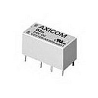
Electromechanical Relay DPDT 3A 12VDC 720Ohm Through Hole
Manufacturer
TE Connectivity
Type
Signal Relayr
Specifications of 9-1393792-7
Contact Arrangement
DPDT
Dc Coil Voltage
12 V
Coil Current
16.67 mA
Mounting
Through Hole
Relay Construction
Non-Latching
Coil Voltage Dc
12V
Contact Form
2 Form C
Voltage Rating (vdc)
220V
Voltage Rating (vac)
250V
Dropout Volt (min)
0.6VDCV
Coil Resistance
720Ohm
Pick-up Voltage (max)
8.4VDC
Maximum Power Rating
60W/125VA
Operate Time
5ms
Contact Current Rating
3A
Contact Material
AgNi/Au
Coil Suppression Diode
No
Push To Test Button
No
Led Indicator
No
Seal
Unsealed
Product Height (mm)
11mm
Product Depth (mm)
10mm
Product Length (mm)
20.2mm
Operating Temp Range
-25C to 85C
Pin Count
8
Mounting Style
Through Hole
Termination Style
PC Pin
Package / Case
DIP
Lead Free Status / Rohs Status
Compliant


Ordering Information
Authorized distributors are more likely to stock the following items.
Ordering Information
Authorized distributors are more likely to stock the following items.
W6 Series
1. Circuit Breaker Mounting:
2. Number of Poles:
3. Circuit Function: (Only X is VDE approved)
4. Actuator: (One actuator per pole)
5. Termination:
6. Maximum Line Voltage: (See Table 1 for current ranges)
7. Time Delay Curve:
8. Amp Rating:
9. VDE Approval:
W9 Series
1. Circuit Breaker Mounting:
2. Number of Poles:
3. Circuit Function: (Only X is VDE approved)
4. Actuator: (One actuator per pole):
5. Maximum Line Voltage: (See Table 1 for current ranges)
6. Time Delay Curve:
7. Amp Rating:
8. VDE Approval:
W91-X112-1
W91-X112-2
W91-X112-3
W91-X112-5
W91-X112-7
W91-X112-10
W67-A2Q12-5
W67-A2Q12-10
W67-X2Q10-3
W67-X2Q10-5
W67-X2Q12-2
W67-X2Q12-3
Dimensions are shown for
reference purposes only.
W = #6-32 mounting threads.
M = M3.0 x 0.5 mounting threads.
67 = Single pole
A = Series trip with auxiliary switch (.093” QC)
1 = Black toggle
2 = White toggle
Q = .250” QC (DIN 46 244) [25A Max. VDE]
Note: “T” termination must be used for all ratings of 31 amps or above.
UL/CSA
TYPES
0 = Instantaneous
2 = Standard delay
3 = Short delay
53 = DC high inrush
0.20
0.25
Blank = UL/CSA approved breaker
V = VDE approved breaker without auxiliary switch
W = #6-32 mounting threads.
91 = Single pole
A = Series trip with auxiliary switch (.093” QC)
1 = Black toggle
UL/CSA
TYPES
0 = Instantaneous
2 = Standard delay
3 = Short delay
53 = DC high inrush
0.20
0.25
0.50
Blank = UL/CSA approved breaker
V = VDE approved breaker without auxiliary switch
0.50
0.75
1 = 277VAC, 50/60 Hz.
2 = 277/480
3 = 250VAC, 400 Hz.
5 = 65VDC
7 = AC/DC 277VAC or 65VDC
1 = 277VAC, 50/60 Hz.
2 = 277/480
3 = 250VAC, 400 Hz.
5 = 65VDC
7 = AC/DC 277VAC or 65VDC
0.75
1.0
1.5
(Delay curve 34 must be specified.)
(Delay curve 34 must be specified.)
W91-X112-15
W91-X112-20
W91-X112-40
W91-X112-50
W91-X113-5
W91-X113-10
W67-X2Q12-5
W67-X2Q12-7
W67-X2Q12-10
W67-X2Q12-15
W67-X2Q12-20
W67-X2Q12-30
1.0
1.5
3 = Black rocker
4 = White rocker
92 = Two pole
2.0
2.5
3.0
68 = Two pole
2.0
2.5
2 = White toggle
10 = AC high inrush (Motor start)
12 = AC high inrush version of #2
13 = AC high inrush version of #3
34 = Combination AC/DC standard delay
10 = AC high inrush (Motor start)
12 = AC high inrush version of #2
13 = AC high inrush version of #3
34 = Combination AC/DC standard delay
M = M3.0 x 0.5 mounting threads.
3.0
3.5
3.5
4.0
5.0
W91-X113-15
W91-X150-5
W91-X152-10
W91-X152-15
W91-X152-20
W91-X152-30
5 = Red rocker
6 = Grey rocker
W67-X2Q13-1
W67-X2Q13-2
W67-X2Q13-3
W67-X2Q13-10
W67-X2Q13-15
W67-X2Q13-20
Dimensions are in inches over
(millimeters) unless otherwise
specified.
93 = Three pole
4.0
5.0
VDE
TYPES
6.0
7 .0
7 .5
VDE
TYPES
69 = Three pole
X = Series trip
S = #8-32 screw [30A Max. VDE]
X = Series trip
6.0
7 .0
1 = 250VAC, 415/240VAC
5 = 65VDC
7 = AC/DC 250VAC, 415/240VAC, 65VDC
1 = 250VAC, 415/240VAC
5 = 65VDC
7 = AC/DC 250VAC, 415/240VAC, 65VDC
W91-X152-40
W91-X152-50
W91-X1110-20
W92-X112-1
W92-X112-2
W92-X112-3
Typical Part No.
W67-X2Q13-25
W67-X2Q13-30
W67-X2Q50-5
W67-X2Q50-10
W67-X2Q52-5
W67-X2Q52-10
9 = Red toggle
(Delay curve 34 must be specified.)
10.0
8.0
9.0
(Delay curve 34 must be specified.
7 .5
8.0
Typical Part No.
94 = Four pole
Catalog 1308242
Notes: Curves may be specified with increased pulse tolerance for 1/2 cycle
11.0
12.0
15.0
Issued 3-03
9.0
10.0
70 = Four pole
Notes: Curves may be specified with increased pulse tolerance for 1/2 cycle by
adding "P" after curve, See delay curve section for availability and details
by adding "P" after curve. See delay curve section for availability and details.
W92-X112-5
W92-X112-7
W92-X112-10
W92-X112-15
W92-X112-20
W92-X112-25
W67-X2Q52-15
W67-X2Q52-20
W67-X2Q52-30
W67-X2Q110-15
W67-X2Q110-20
W68-X2Q12-3
B
Specifications and availability
subject to change.
11.0
12.0
20.0
25.0
30.0
W 67- X
T = #10-32 screw [50A Max. VDE]
B
15.0
20.0
)
W
35.0
40.0
45.0
W92-X112-30
W92-X112-40
W92-X112-50
W92-X113-15
W92-X113-20
W92-X1110-20
W68-X2Q12-5
W68-X2Q12-7
W68-X2Q12-10
W68-X2Q12-15
W68-X2Q12-20
W68-X2Q12-25
25.0
30.0
91- X
50.0
Consult factory for other values
35.0
40.0
2
Q
45.0
50.0
1
W92-X1110-30
W93-X112-5
W93-X112-10
W93-X112-15
W93-X112-20
W93-X112-25
W68-X2Q12-30
W68-X2Q13-15
W68-X2Q110-10
W68-X2Q110-20
W69-X2Q12-5
W69-X2Q12-10
1
Consult factory for
other values.
1
.
2-
2- 20
www.tycoelectronics.com
Technical support:
Refer to inside back cover.
W93-X112-30
W93-X112-40
W93-X112-50
W93-X1110-20
W93-X1110-30
W69-X2Q12-15
W69-X2Q12-20
W69-X2Q12-25
W69-X2Q12-30
W69-X2Q110-20
W69-X2Q110-30
20
P&B
121
Related parts for 9-1393792-7
Image
Part Number
Description
Manufacturer
Datasheet
Request
R

Part Number:
Description:
CRIMP, RECEPTACLE
Manufacturer:
TE Connectivity
Datasheet:

Part Number:
Description:
PIGGYBACK DISCONNECT, 6.35MM, CRIMP BLUE
Manufacturer:
TE Connectivity
Datasheet:

Part Number:
Description:
Manufacturer:
TE Connectivity
Datasheet:

Part Number:
Description:
CRIMP TERMINAL, FEMALE, BLUE
Manufacturer:
TE Connectivity
Datasheet:
Part Number:
Description:
Manufacturer:
TE Connectivity
Datasheet:

Part Number:
Description:
CONN HEADR BRKWAY .100 13POS R/A
Manufacturer:
Tyco Electronics
Datasheet:
Part Number:
Description:
CONN HEADR BRKWAY .100 13POS R/A
Manufacturer:
Tyco Electronics
Datasheet:
Part Number:
Description:
CONN HDR BRKWAY .100 13POS VERT
Manufacturer:
Tyco Electronics
Datasheet:
Part Number:
Description:
CONN HDR BRKWAY .100 13POS VERT
Manufacturer:
Tyco Electronics
Datasheet:
Part Number:
Description:
CONN HDR BRKWAY .100 13POS VERT
Manufacturer:
Tyco Electronics
Datasheet:
Part Number:
Description:
CONN HEADR BRKWAY .100 13POS R/A
Manufacturer:
Tyco Electronics
Datasheet:
Part Number:
Description:
CONN HEADR BRKWAY .100 13POS STR
Manufacturer:
Tyco Electronics
Datasheet:
Part Number:
Description:
CONN HEADR BRKWAY .100 13POS STR
Manufacturer:
Tyco Electronics
Datasheet:
Part Number:
Description:
CONN HEADR BRKWAY .100 13POS STR
Manufacturer:
Tyco Electronics
Datasheet:
Part Number:
Description:
CONN HEADR BRKWAY .100 13POS R/A
Manufacturer:
Tyco Electronics
Datasheet: