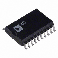
AD8804AR Analog Devices Inc, AD8804AR Datasheet - Page 15

AD8804AR
Manufacturer Part Number
AD8804AR
Description
IC DAC 8BIT 12CH W/SD 20-SOIC
Manufacturer
Analog Devices Inc
Series
TrimDAC®r
Datasheet
1.AD8804ARUZ-REEL.pdf
(16 pages)
Specifications of AD8804AR
Rohs Status
RoHS non-compliant
Settling Time
600ns
Number Of Bits
8
Data Interface
Serial
Number Of Converters
12
Voltage Supply Source
Single Supply
Power Dissipation (max)
60µW
Operating Temperature
-40°C ~ 85°C
Mounting Type
Surface Mount
Package / Case
20-SOIC (7.5mm Width)
Available stocks
Company
Part Number
Manufacturer
Quantity
Price
Part Number:
AD8804AR
Manufacturer:
ADI/亚德诺
Quantity:
20 000
Part Number:
AD8804ARU
Manufacturer:
ADI/亚德诺
Quantity:
20 000
Part Number:
AD8804ARUZ
Manufacturer:
ADI/亚德诺
Quantity:
20 000
Part Number:
AD8804ARZ
Manufacturer:
ADI/亚德诺
Quantity:
20 000
REV. 0
attenuation the optional circuitry inside the dashed box may be
removed and replaced with a direct connection from O1 of
AD8802/AD8804 to Pin 11 of SSM2018T.
When high gain resolution is desired, V
decoupled from the power rails and shifted closer together.
This technique increases the gain resolution with the unfortu-
nate penalty of decreased gain range.
A Digitally Controlled LM1204 150 MHz RGB Amplifier
System
The LM1204 is an industry standard video amplifier system.
Figure 29 illustrates a configuration that removes the usual
seven level setting potentiometers and replaces them with only
one IC. The AD8802/AD8804, in addition to being smaller
and more reliable than mechanical potentiometers, has the
added feature of digital control.
The REF195 is a 5.0 V reference used to supply both the power
and reference voltages to the AD8802/AD8804. This is possible
because of the high reference output current available (30 mA
typical) together with the low power consumption of the
AD8802/AD8804.
A Low Noise 90 MHz Programmable Gain Amplifier
The AD603 is a low noise, voltage-controlled amplifier for use
in RF and IF AGC systems. It provides accurate, pin selectable
gains of –11 dB to +31 dB with a bandwidth of 90 MHz or
+9 dB to +51 dB with a bandwidth of 9 MHz. Any intermedi-
ate gain range may be arranged using one external resistor
VIDEO
INPUT
RGB
TO µC
5
7, 11, 17
Figure 29. A Digitally Controlled LM1204—150 MHz RGB Amplifier System
+12V
CS
CLK
SDI
V
O1 O2 O3 04 O5 O6 O7 V
CC
20
LM1204
21
9
22
AD8802/4
13
43
O1 = 2V
O2 = CONTRAST
O3 = BP CLAMP WIDTH ADJUST
O4 = BLANK LEVEL ADJUST
REFH
15
24
BLANK GATE
(FOR BRIGHTNESS CONTROL)
38, 28, 33
and V
R GAIN
B GAIN
G GAIN
INPUT
40, 35, 30
REFH
–H SYNC
OUTPUT
REFL
V
(+12V)
+4V
CC
may be
0.1µF
–15–
10µF
RGB FEEDBACK
between Pins 5 and 7. The input referred noise spectral density
is only 1.3 nV Hz and power consumption is 125 mW at the
recommended 5 V supplies.
The decibel gain is “linear in dB,” accurately calibrated, and
stable over temperature and supply. The gain is controlled at a
high impedance (50 M ), low bias (200 nA) differential input;
the scaling is 25 mV/dB, requiring a gain-control voltage of only
1 V to span the central 40 dB of the gain range. An overrange
and underrange of 1 dB is provided whatever the selected
range. The gain-control response time is less than 1 s for a 40
dB change. The settling time of the AD8802/AD8804 to within
a 1/2 LSB band is 0.6 s making it an excellent choice for con-
trol of the AD603.
The differential gain-control interface allows the use of either
differential or single-ended positive or negative control voltages,
where the common-mode range is –1.2 V to 2.0 V. Once again
the AD8802/AD8804 is ideally suited to provide the differential
input range of 1 V within the common-mode range of 0 V to
2 V. To accomplish this, place V
1.0 V, then all 256 voltage levels of the AD8804 will fall within
the gain-control range of the AD603. Please refer to the AD603
data sheet for further information regarding gain control, layout,
and general operation.
The dual OP279 is a rail-to-rail op amp used in Figure 30 to
drive the inputs V
are low impedance (2 k typical).
O5 = R AGAIN
O6 = B AGAIN
O7 = G AGAIN
O8 – O12 = NOT USED
OUT
REF195
GND
IN
REFH
10µF
and V
0.1µF
REFL
CRT
VIDEO
AMP
+12V
V
REFH
CC
because these reference inputs
AD8802/AD8804
at 2.0 V and V
CRT
CATHODE
REFL
at


