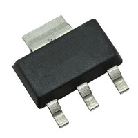
SX8652IWLTRT Semtech, SX8652IWLTRT Datasheet - Page 14

SX8652IWLTRT
Manufacturer Part Number
SX8652IWLTRT
Description
IC TOUCH SCREEN CTRLR 14DFN
Manufacturer
Semtech
Type
Resistiver
Datasheet
1.SX8652IWLTRT.pdf
(29 pages)
Specifications of SX8652IWLTRT
Touch Panel Interface
4-Wire, 5-Wire
Number Of Inputs/keys
2 Key
Resolution (bits)
12 b
Data Interface
Serial, SPI™
Data Rate/sampling Rate (sps, Bps)
74k
Voltage Reference
Internal
Voltage - Supply
1.65 V ~ 3.7 V
Current - Supply
10mA
Operating Temperature
-40°C ~ 85°C
Mounting Type
Surface Mount
Package / Case
14-DFN
Voltage Supply Source
Single Supply
Sampling Rate (per Second)
74k
Lead Free Status / RoHS Status
Lead free / RoHS Compliant
Other names
SX8652IWLTR
Available stocks
Company
Part Number
Manufacturer
Quantity
Price
Company:
Part Number:
SX8652IWLTRT
Manufacturer:
COXOC
Quantity:
40 000
5. 5-wire Touch Screen Detailed Description
5.1. Touch Screen Operation
As the 4-wire, the 5-wire resistive touch screen consists of two resistive
sheets separated by an insulator (Figure 11). The main difference is that
the 4 wires are connected on the 4 corners of the bottom conductive
sheet. They are referred as Top Left, Top Right, Bottom Left, Bottom
Right.
The fifth wire is embedded in the top sheet and is used for sensing the
electrode voltage and is referred as the wiper.
5.2. Coordinates Measurement
When the electrodes TL is connected with BL and TR with BR, they form with the linearization pattern 2 electrodes bars
which are very similar to the X electrodes in a 4-wire touchscreen. In the same way, the association of TL with TR and BL
with BR create Y electrodes.
The four corners are therefore able to produce voltage gradients in the horizontal and vertical axis. The wiper is connected
to the high input impedance of the ADC. When a pressure is applied on the top sheet, the contact point split the bottom
sheet resistance into R1 and R2 on the X axis and R3 and R4 on the Y axis.
The X and Y position converted by the 12-bit ADC
gives the following result.
5.3. Pen Detection
The BR pin is connected to the positive pin of the reference voltage through
R
grounding path for a screen touch event.
The BR pin is monitored to detect voltage drop. When a pressure is applied on
the top surface, a current path is created between the two layers and the
PENIRQ bit of the RegStat register will be set. R
greatest value of 200 kOhm for optimal detection (see Table 15). Increasing
PowDly settings can also improve the detection on panel with high resistance.
In PENDET mode, the pen detection will set NIRQ low.
Revision V1.7/October 2010
©2010 Semtech Corp.
ADVANCED COMMUNICATIONS & SENSING
PNDT
. The wiper panel is grounded at the AUX/WIPER pin to provide the
PNDT
15kV ESD Low Power 4-Wire / 5-Wire Resistive
should be set to the
Page 14
Touchscreen Controller with SPI Interface
Xpos
=
4095
Figure 12. 5-wire pen detection circuitry
------------------- -
R1
Vref
+
-
R2
+
Figure 11. 5-wire touchscreen
R2
Ypos
WIPER
AUX/
Bottom
layer
layer
Top
BR
R1
R PNDT
-
=
www.semtech.com
DATASHEET
SX8652
4095
Internal
logic
Sb
Rb
------------------- -
R3
Q
Q
R4
+
R4


