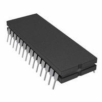
AD7871TQ Analog Devices Inc, AD7871TQ Datasheet

AD7871TQ
Specifications of AD7871TQ
Related parts for AD7871TQ
AD7871TQ Summary of contents
Page 1
FEATURES Complete Monolithic 14-Bit ADC 2s Complement Coding Parallel, Byte and Serial Digital Interface 80 dB SNR at 10 kHz Input Frequency 57 ns Data Access Time Low Power—50 mW typ 83 kSPS Throughput Rate 16-Lead SOIC (AD7872) APPLICATIONS ...
Page 2
AD7871/AD7872–SPECIFICATIONS Parameter 2 DYNAMIC PERFORMANCE 3 Signal-to-Noise Ratio (SNR MIN MAX Total Harmonic Distortion (THD) Peak Harmonic or Spurious Noise Intermodulation Distortion (IMD) Second Order Terms Third Order Terms Track/Hold Acquisition Time DC ACCURACY ...
Page 3
TIMING CHARACTERISTICS Limit MIN MAX Parameter ( Versions) (T Version ...
Page 4
AD7871/AD7872 AD7871 PIN FUNCTION DESCRIPTION DIP No. Mnemonic Function 1 CONVST Convert Start. A low to high transition on this input puts the track/hold into the hold mode. This input is asynchronous to the CLK. CS and RD must be ...
Page 5
AD7872 PIN FUNCTION DESCRIPTION DIP No. Mnemonic Function 1 CONTROL Control Input. With this pin the SCLK is noncontinuous; with this pin at –5 V, the SCLK is continuous. 2 CONVST Convert Start. A low to high ...
Page 6
AD7871/AD7872 CONVERTER DETAILS The AD7871/AD7872 is a complete 14-bit A/D converter, re- quiring no external components apart from power supply decoupling capacitors comprised of a 14-bit successive ap- proximation ADC based on a fast settling voltage-output DAC, a ...
Page 7
Gain error can be adjusted at either the first code transition (ADC negative full scale) or the last code transition (ADC posi- tive full scale). The trim procedures for both cases are as follows (see Figure 6). Positive Full-Scale Adjust ...
Page 8
AD7871/AD7872 placed on the data bus. These six bits are right justified and thereby occupy the lower six bits of the byte while the upper two bits are zeros. Serial Output Format Serial data is available on the AD7871 when ...
Page 9
Figure 10. Mode 1 Timing Diagram, Byte or Serial Read Figure 11. Mode 2 Timing Diagram, 14-Bit Parallel Read Figure 12. Mode 2 Timing Diagram, Byte or Serial Read REV. D AD7871/AD7872 –9– ...
Page 10
AD7871/AD7872 DYNAMIC SPECIFICATIONS The AD7871/AD7872 is specified and tested for dynamic per- formance specifications as well as traditional dc specifications such as Integral and Differential Nonlinearity. These ac specifi- cations are required for signal processing applications such as Speech Recognition, ...
Page 11
Using the CCIF standard where two input frequencies near the top end of the input bandwidth are used, the second and third or- der terms are of different significance. The second order terms are usually distanced in frequency from the ...
Page 12
AD7871/AD7872 Serial Interfacing Both the AD7871 and the AD7872 have an identical serial in- terface. The diagrams that follow show the AD7872 interfaces only, but the AD7871 could just as easily be used in these cir- cuits. Figures 19, 20 ...
Page 13
LAYOUT HINTS Ensure that the layout for the printed circuit board has the digi- tal and analog signal lines separated as much as possible. Take care not to run a digital track alongside an analog signal track. Guard (screen) the ...
Page 14
AD7871/AD7872 Figure 24. Data Acquisition Circuit Using the AD7871/AD7872 Figure 25. PCB Silkscreen for Figure 24 –14– REV. D ...
Page 15
Figure 26. PCB Component Side Layout for Figure 24 REV. D Figure 27. PCB Solder Side Layout for Figure 24 –15– AD7871/AD7872 ...
Page 16
... dBs min AD7871JP + dBs min AD7871KP + dBs min 4 AD7871TQ – +125 C 79 dBs min NOTES 1 To order MIL-STD-883, Class B, processed parts, add /883B to part number. Contact local sales office for military data sheet. 2 Contact local sales office for LCCC availability Plastic DIP Plastic Leaded Chip Carrier (PLCC);Q = Cerdip. ...


