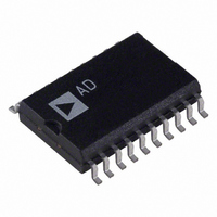
AD7703BR Analog Devices Inc, AD7703BR Datasheet - Page 10

AD7703BR
Manufacturer Part Number
AD7703BR
Description
IC ADC 20BIT LC2MOS 20-SOIC
Manufacturer
Analog Devices Inc
Datasheet
1.AD7703AR-REEL.pdf
(16 pages)
Specifications of AD7703BR
Rohs Status
RoHS non-compliant
Number Of Bits
20
Sampling Rate (per Second)
4k
Data Interface
Serial
Number Of Converters
1
Power Dissipation (max)
37mW
Voltage Supply Source
Analog and Digital, Dual ±
Operating Temperature
-40°C ~ 85°C
Mounting Type
Surface Mount
Package / Case
20-SOIC (0.300", 7.50mm Width)
Available stocks
Company
Part Number
Manufacturer
Quantity
Price
Part Number:
AD7703BRZ
Manufacturer:
ADI/亚德诺
Quantity:
20 000
Company:
Part Number:
AD7703BRZ-REEL
Manufacturer:
INTERSIL
Quantity:
409
AD7703
Initiating Calibration
Table III illustrates the calibration modes available in the AD7703.
Not shown in the table is the function of the BP/UP pin, which
determines whether the converter has been calibrated to mea-
sure bipolar or unipolar signals. A calibration step is initiated by
bringing the CAL pin high for at least four CLKIN cycles and
then bringing it low again. The states of SC1 and SC2 along
with the BP/UP pin will determine the type of calibration to be
performed. All three signals should be stable before the CAL
pin is taken positive. The SC1 and SC2 inputs are latched when
CAL goes high. The BP/UP input is not latched and, therefore,
must remain in a fixed state throughout the calibration and
measurement cycles. Any time the state of the BP/UP is changed,
a new calibration cycle must be performed to enable the AD7703
to function properly in the new mode.
When a calibration step is initiated, the DRDY signal will go high
and remain high until the step is finished. Table III shows the
number of clock cycles each calibration requires. Once a calibra-
tion step is initiated, it must finish before a new calibration step
can be executed. In the two step system calibration mode, the
offset calibration step must be initiated before initiating the gain
calibration step.
CAL
*DRDY remains high throughout the calibration sequence. In the Self-Calibration mode, DRDY falls once the AD7703 has settled to the analog input. In all other
modes, DRDY falls as the device begins to settle.
SC1
0
1
0
1
Calibration Mode
Self-Calibration
System Calibration
SC2
0
1
1
0
Calibration
Type
Self-Calibration
System Offset
System Gain
System Offset
Zero Scale
V
S
OFF
AGND
Table IV. Output Code Size After Calibration
Table III. Calibration Truth Table*
Zero-Scale
Calibration
V
A
A
AGND
IN
IN
Gain Factor
V
S
GAIN
REF
–10–
When self-calibration is completed, DRDY falls and the output
port is updated with a data-word that represents the analog input
signal. When a system calibration step is completed, DRDY will
fall and the output port will be updated with the appropriate data
value (all 0s for the zero-scale point and all 1s for the full-scale
point). In the system calibration mode, the digital filter must
settle before the output code will represent the value of the
analog input signal. Tables IV and V indicate the output code
size and output coding of the AD7703 in its various modes. In
these tables, S
S
Span and Offset Limits
Whenever a system calibration mode is used, there are limits
on the amount of offset and span that can be accommodated.
The range of input span in both the Unipolar and Bipolar
modes has a minimum value of 0.8 V
value of 2(V
The amount of offset that can be accommodated depends on
whether the Unipolar or Bipolar mode is being used. In Unipolar
mode, the system calibration modes can handle a maximum
offset of 0.2 V
Therefore the AD7703 in the Unipolar mode can be calibrated
to mimic bipolar operation.
Full-Scale
Calibration
V
A
V
GAIN
REF
IN
REF
is the measured system gain at the full-scale point in volts.
Unipolar
(V
(S
GAIN
REF
1048576
REF
1048576
OFF
REF
–V
+ 0.1 V).
– S
and a minimum offset of –(V
is the measured system offset in volts and
AGND
OFF
Sequence
One Step
First Step
Second Step
One Step
)
)
1 LSB
Bipolar
2(V
2(S
1048576
GAIN
REF
1048576
Calibration
Time
3,145,655 Clock Cycles
1,052,599 Clock Cycles
1,068,813 Clock Cycles
2,117,389 Clock Cycles
REF
–V
– S
and a maximum
AGND
OFF
)
REF
)
+ 0.1 V).
REV. E


