AD7701BN Analog Devices Inc, AD7701BN Datasheet - Page 7
AD7701BN
Manufacturer Part Number
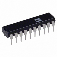
AD7701BN
Description
IC ADC 16BIT LC2MOS MONO 20-DIP
Manufacturer
Analog Devices Inc
Datasheet
1.AD7701ARZ.pdf
(20 pages)
Specifications of AD7701BN
Rohs Status
RoHS non-compliant
Number Of Bits
16
Sampling Rate (per Second)
4k
Data Interface
Serial
Number Of Converters
1
Power Dissipation (max)
37mW
Voltage Supply Source
Analog and Digital, Dual ±
Operating Temperature
-40°C ~ 85°C
Mounting Type
Through Hole
Package / Case
20-DIP (0.300", 7.62mm)
Available stocks
Company
Part Number
Manufacturer
Quantity
Price


Figure 1. Load Circuit for Access
Time and Bus Relinquish Time
DEFINITION OF TERMS
Linearity Error
This is the maximum deviation of any code from a straight line
passing through the endpoints of the transfer function. The
endpoints of the transfer function are zero scale (not to be
confused with bipolar zero), a point 0.5 LSB below the first
code transition (000 . . . 000 to 000 . . . 001) and full scale, a
point 1.5 LSB above the last code transition (111 . . . 110 to
111 . . . 111). The error is expressed as a percentage of full scale.
Differential Linearity Error
This is the difference between any code’s actual width and the
ideal (1 LSB) width. Differential linearity error is expressed in
LSBs. A differential linearity specification of ± 1 LSB or less
guarantees monotonicity.
Positive Full-Scale Error
Positive full-scale error is the deviation of the last code transition
(111 . . . 110 to 111 . . . 111) from the ideal (V
It applies to both positive and negative analog input ranges and
is expressed in microvolts.
Unipolar Offset Error
Unipolar offset error is the deviation of the first code transition
from the ideal (AGND + 0.5 LSB) when operating in the Uni-
polar mode. It is expressed in microvolts.
REV. E
CLKIN
SDATA
SCLK
CS
OUTPUT
Figure 3. SSC Mode Data
Hold Time
SDATA
PIN
TO
HI-Z
CS
100pF
t
t
6
Figure 5. SSC Mode Timing Diagram
4
C
L
VALID
DATA
DB15
t
7
t
10
t
I
8
I OH
DB14
OL
t
200µA
5
1.6mA
HI-Z
+
2.1V
Figure 2a. Calibration Control Timing
Figure 4a. SEC Mode Data Hold Time
SC1, SC2
DB1
CAL
REF
SDATA
± 3/2 LSBs).
DB0
CS
t
5
SC1, SC2 VALID
VALID
DATA
t
1
HI-Z
HI-Z
t
15
–7–
t
HI-Z
2
Bipolar Zero Error
This is the deviation of the midscale transition (0111 . . . 111 to
1000 . . . 000) from the ideal (AGND – 0.5 LSB) when operating
in the Bipolar mode. It is expressed in microvolts.
Bipolar Negative Full-Scale Error
This is the deviation of the first code transition from the ideal
(–V
expressed in microvolts.
Positive Full-Scale Overrange
Positive full-scale overrange is the amount of overhead available
to handle input voltages greater than +V
peaks or excess voltages due to system gain errors in system
calibration routines) without introducing errors due to overloading
the analog modulator or overflowing the digital filter. It is
expressed in millivolts.
Negative Full-Scale Overrange
This is the amount of overhead available to handle voltages below
–V
the digital filter. Note that the analog input will accept negative
voltage peaks even in the Unipolar mode. The overhead is
expressed in millivolts.
SDATA
DRDY
SCLK
REF
REF
CS
without overloading the analog modulator or overflowing
+ 0.5 LSB) when operating in the Bipolar mode. It is
t
HI-Z
17
Figure 6. AC Mode Timing Diagram
t
18
DRDY
SDATA
SCLK
START
Figure 4b. SEC Mode Timing Diagram
CS
t
CLKIN
SLEEP
Figure 2b. SLEEP Mode Timing
13
DB8
HIGH BYTE
HI-Z
DB15 DB14
DB9
t
LOW BYTE
11
t
14
DB7
REF
t
12
(for example, noise
STOP 1
AD7701
t
3
STOP 2
DB1
t
19
DB0
HI-Z
t
16
HI-Z
Related parts for AD7701BN
Image
Part Number
Description
Manufacturer
Datasheet
Request
R

Part Number:
Description:
±1.7g Dual-Axis IMEMS Accelerometer Evaluation Board
Manufacturer:
Analog Devices Inc
Datasheet:

Part Number:
Description:
Inertial Sensor Evaluation System
Manufacturer:
Analog Devices Inc
Datasheet:
Part Number:
Description:
Manufacturer:
Analog Devices Inc
Datasheet:
Part Number:
Description:
Manufacturer:
Analog Devices Inc
Datasheet:
Part Number:
Description:
Manufacturer:
Analog Devices Inc
Datasheet:
Part Number:
Description:
Manufacturer:
Analog Devices Inc
Datasheet:
Part Number:
Description:
Manufacturer:
Analog Devices Inc
Datasheet:
Part Number:
Description:
Manufacturer:
Analog Devices Inc
Datasheet:
Part Number:
Description:
Manufacturer:
Analog Devices Inc
Datasheet:
Part Number:
Description:
Manufacturer:
Analog Devices Inc
Datasheet:
Part Number:
Description:
Manufacturer:
Analog Devices Inc
Datasheet:
Part Number:
Description:
Manufacturer:
Analog Devices Inc
Datasheet:
Part Number:
Description:
Manufacturer:
Analog Devices Inc
Datasheet: