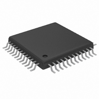
MAX1182ECM+D Maxim Integrated Products, MAX1182ECM+D Datasheet - Page 17

MAX1182ECM+D
Manufacturer Part Number
MAX1182ECM+D
Description
IC ADC 10BIT 65MSPS DUAL 48-TQFP
Manufacturer
Maxim Integrated Products
Datasheet
1.MAX1182ECMD.pdf
(21 pages)
Specifications of MAX1182ECM+D
Number Of Bits
10
Sampling Rate (per Second)
65M
Data Interface
Parallel
Number Of Converters
2
Power Dissipation (max)
240mW
Voltage Supply Source
Single Supply
Operating Temperature
-40°C ~ 85°C
Mounting Type
Surface Mount
Package / Case
48-TQFP Exposed Pad, 48-eTQFP, 48-HTQFP, 48-VQFP
Conversion Rate
65 MSPs
Resolution
10 bit
Snr
59.5 dB
Voltage Reference
2.048 V
Supply Voltage (max)
3.6 V
Supply Voltage (min)
2.7 V
Maximum Power Dissipation
2430 mW
Maximum Operating Temperature
+ 85 C
Mounting Style
SMD/SMT
Input Voltage
3 V
Minimum Operating Temperature
- 40 C
Lead Free Status / RoHS Status
Lead free / RoHS Compliant
Integral nonlinearity is the deviation of the values on an
actual transfer function from a straight line. This straight
line can be either a best straight-line fit or a line drawn
between the endpoints of the transfer function, once
offset and gain errors have been nullified. The static lin-
earity parameters for the MAX1182 are measured using
the best straight-line fit method.
Differential nonlinearity is the difference between an
actual step-width and the ideal value of 1 LSB. A DNL
Figure 6. Transformer-Coupled Input Drive
with Internal Reference and Parallel Outputs
Static Parameter Definitions
Differential Nonlinearity (DNL)
Dual 10-Bit, 65Msps, 3V, Low-Power ADC
______________________________________________________________________________________
Integral Nonlinearity (INL)
V
V
IN
IN
0.1μF
0.1μF
N.C.
N.C.
MINICIRCUITS
MINICIRCUITS
3
3
1
1
2
2
TT1–6
TT1–6
T1
T1
6
5
4
6
5
4
2.2μF
2.2μF
25Ω
25Ω
25Ω
25Ω
0.1μF
0.1μF
22pF
22pF
22pF
22pF
error specification of less than 1 LSB guarantees no
missing codes and a monotonic transfer function.
Figure 9 depicts the aperture jitter (t
sample-to-sample variation in the aperture delay.
Aperture delay (t
falling edge of the sampling clock and the instant when
an actual sample is taken (Figure 9).
Dynamic Parameter Definitions
INA+
COM
INA-
INB+
INB-
MAX1182
AD
) is the time defined between the
Aperture Delay
Aperture Jitter
AJ
), which is the
17


