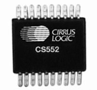
CS5523-ASZ Cirrus Logic Inc, CS5523-ASZ Datasheet - Page 47

CS5523-ASZ
Manufacturer Part Number
CS5523-ASZ
Description
IC ADC 16BIT SIG/DELT 24-SSOP
Manufacturer
Cirrus Logic Inc
Specifications of CS5523-ASZ
Number Of Converters
1
Package / Case
24-SSOP
Number Of Bits
16
Data Interface
Serial
Power Dissipation (max)
10mW
Voltage Supply Source
Analog and Digital
Operating Temperature
-40°C ~ 85°C
Mounting Type
Surface Mount
Number Of Adc Inputs
1
Architecture
Delta-Sigma
Conversion Rate
617 SPs
Resolution
24 bit
Input Type
Voltage
Interface Type
Serial (3-Wire)
Voltage Reference
2.5 V
Supply Voltage (max)
5 V
Supply Voltage (min)
25 mV
Maximum Power Dissipation
500 mW
Maximum Operating Temperature
+ 85 C
Mounting Style
SMD/SMT
Input Voltage
25 mV to 5 V
Minimum Operating Temperature
- 40 C
Lead Free Status / RoHS Status
Lead free / RoHS Compliant
Lead Free Status / RoHS Status
Lead free / RoHS Compliant, Lead free / RoHS Compliant
Other names
598-1105-5
Available stocks
Company
Part Number
Manufacturer
Quantity
Price
Part Number:
CS5523-ASZ
Manufacturer:
CIRRUSLOGIC
Quantity:
20 000
Once the RS bit has been set to ‘0’, the ADC is
placed in the command state were it waits for a val-
id command to execute. The next step is to load the
configuration register and then the channel setup
registers with conditions that you have decided. If
you need to do a factory calibration, perform offset
and gain calibrations for each channel that is to be
used. Then off-load the offset and gain register
contents into EEPROM. These registers can then
be initialized to these conditions when the instru-
ment is used in normal operation. Once calibration
is ready, input the command to start conversions in
DS317F4
configuration register. Note that while the RS
bit is set to ‘1’ all other register bits in the ADC
will be reset to their default state, and the RS bit
must be set to ‘0’ for normal operation of the
converters.
the mode you have selected via the configuration
register bits. Monitor the SDO pin for a flag that the
data is ready and read conversion data.
2.11 PCB Layout
The CS5521/22/23/24/28 should be placed entirely
over an analog ground plane with both the AGND
and DGND pins of the device connected to the an-
alog plane. Place the analog-digital plane split im-
mediately adjacent to the digital portion of the chip.
If separate digital (VD+) and analog (VA+) sup-
plies are used, it is recommended that a diode be
placed between them (the cathode of the diode
should point to VA+). If the digital supply comes
up before the analog supply, the ADC may not start
up properly.
CS5521/22/23/24/28
47


