DS1746WP-120+ Maxim Integrated Products, DS1746WP-120+ Datasheet
DS1746WP-120+
Specifications of DS1746WP-120+


Related parts for DS1746WP-120+


DS1746WP-120+ Summary of contents
Page 1
FEATURES Integrated NV SRAM, Real-Time Clock, Crystal, Power-Fail Control Circuit, and Lithium Energy Source Clock Registers are Accessed Identically to the Static RAM. These Registers are Resident in the Eight Top RAM Locations. Century Byte Register ...
Page 2
PIN DESCRIPTION PIN NAME PDIP PowerCap 33 A16 3 32 A14 4 30 A12 ...
Page 3
... DS1746P-70IND+ 5.0 DS1746W-120+ 3.3 DS1746W-120IND+ 3.3 DS1746WP-120+ 3.3 DS1746WP-120IND+ 3.3 +Denotes a lead(Pb)-free/RoHS-compliant package. The top mark will include a “+” symbol on lead-free devices. *DS9034-PCX+ or DS9034I-PCX+ required (must be ordered separately). † An “IND” anywhere on the top mark denotes an industrial temperature grade device. ...
Page 4
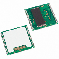
Figure 1. Block Diagram PACKAGES The DS1746 is available in two packages (32-pin DIP and 34-pin PowerCap module). The 32-pin DIP style module integrates the crystal, lithium energy source, and silicon all in one package. The 34-pin PowerCap Module Board ...
Page 5
Table 1. Truth Table > <V < <V < SETTING THE CLOCK As shown in Table ...
Page 6
Table 2. Register Map ADDRESS B7 B6 1FFFF 10 Year 1FFFE X X 1FFFD X X 1FFFC BF FT 1FFFB X X 1FFFA X OSC 1FFF9 1FFF8 W R OSC = Stop Bit R = Read Bit W = Write ...
Page 7
DATA-RETENTION MODE The 5V device is fully accessible and data can be written or read only when V However, when V is below the power-fail point internal clock registers and SRAM are blocked from any access. At this ...
Page 8
ABSOLUTE MAXIMUM RATINGS Voltage Range on Any Pin Relative to Ground..………………………………..……………………..-0.3V to +6.0V Storage Temperature Range EDIP ...................................................……………………...………………..……………….-40°C to +85°C PowerCap ................................................................................................................………...-55°C to +125°C Lead Temperature (soldering, 10s)…........................................................................................……………….+260°C Note: EDIP is hand or wave-soldered only. Soldering Temperature (reflow, PowerCap)......................................................................................…………+260° This ...
Page 9
DC ELECTRICAL CHARACTERISTICS = 3.3V 10 Over the Operating Range PARAMETER Active Supply Current TTL Standby Current ( CMOS Standby Current ( CE V -0.2V) CC Input Leakage Current (any ...
Page 10
AC CHARACTERISTICS—READ CYCLE (3.3V) = 3.3V 10 Over the Operating Range PARAMETER Read Cycle Time Address Access Time Low-Z CE Access Time CE Data Off Time Low-Z OE Access ...
Page 11
AC CHARACTERISTICS—WRITE CYCLE (5V) = 5.0V 10 Over the Operating Range PARAMETER Write Cycle Time Address Setup Time WE Pulse Width CE Pulse Width Data Setup Time Data Hold Time Data Hold Time WE Data ...
Page 12
WRITE CYCLE TIMING DIAGRAM, WRITE-ENABLE CONTROLLED A0-A16 WEZ DQ0-DQ7 DATA OUTPUT WRITE CYCLE TIMING DIAGRAM, CHIP-ENABLE CONTROLLED A0-A16 DQ0-DQ7 DS1746/DS1746P Y2K-Compliant, Nonvolatile Timekeeping RAMs VALID t t WEW ...
Page 13
POWER-UP/DOWN AC CHARACTERISTICS—5V = 5.0V 10 Over the Operating Range PARAMETER Before Power-Down V Fall Time PF(MAX) V PF(MIN) V Fall Time ...
Page 14
POWER-UP/DOWN CHARACTERISTICS—3.3V = 3.3V 10 Over the Operating Range PARAMETER Before H Power-Down V Fall Time PF(MAX) V PF(MIN) V Rise Time PF(MIN) ...
Page 15
AC TEST CONDITIONS Output Load: 50pF + 1TTL Gate Input Pulse Levels 3.0V Timing Measurement Reference Levels: Input: 1.5V Output: 1.5V Input Pulse Rise and Fall Times: 5ns NOTES: 1) Voltages are referenced to ground. 2) Typical values ...
Page 16
... Maxim reserves the right to change the circuitry and specifications without notice at any time 2010 Maxim Integrated Products DS1746/DS1746P Y2K-Compliant, Nonvolatile Timekeeping RAMs DESCRIPTION as specified by RAM vendors Maxim and the Dallas logo are registered trademarks of Maxim Integrated Products. PAGES CHANGED ...