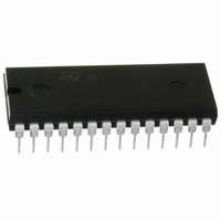
M48T35Y-70PC1 STMicroelectronics, M48T35Y-70PC1 Datasheet - Page 18

M48T35Y-70PC1
Manufacturer Part Number
M48T35Y-70PC1
Description
IC TIMEKPR NVRAM 256KBIT 5V 28DI
Manufacturer
STMicroelectronics
Series
Timekeeper®r
Type
Clock/Calendar/NVSRAMr
Specifications of M48T35Y-70PC1
Memory Size
256K (32K x 8)
Time Format
HH:MM:SS (24 hr)
Date Format
YY-MM-DD-dd
Interface
Parallel
Voltage - Supply
4.5 V ~ 5.5 V
Operating Temperature
0°C ~ 70°C
Mounting Type
Through Hole
Package / Case
28-DIP Module (600 mil), 28-EDIP
Function
Clock/Calendar/NV Timekeeping RAM/Watchdog Timer/Battery Backup
Rtc Memory Size
32768 Byte
Supply Voltage (max)
5.5 V
Supply Voltage (min)
4.5 V
Maximum Operating Temperature
+ 70 C
Minimum Operating Temperature
0 C
Mounting Style
Through Hole
Rtc Bus Interface
Parallel
Capacitance, Input
10 pF
Capacitance, Load
100 pF
Capacitance, Output
10 pF
Current, Input, Leakage
±1 μA
Current, Leakage Input
± 1 μA (Max.)
Current, Operating
30 mA
Current, Output, Leakage
±1
Current, Supply
30 mA (Max.)
Data Retention
10 yrs.
Density
256K
Frequency, Crystal
32768
Memory Type
SRAM
Organization
32K×8
Package Type
PDIP28
Power Dissipation
1 W
Temperature, Operating
0 to +70 °C
Temperature, Operating, Maximum
+70 °C
Temperature, Operating, Minimum
0 °C
Time, Access
70 ns
Time, Fall
≤5 ns
Time, Read Cycle
70 ns
Time, Rise
≤5 ns
Time, Write Cycle
70 ns
Voltage, Input Range
-0.3 to 7 V
Voltage, Input, High
4.8 to 5.8 V
Voltage, Input, Low
0.8 V
Voltage, Output, High
2.4 V
Voltage, Output, Low
0.4 V
Voltage, Supply
4.5 to 5.5 V
Lead Free Status / RoHS Status
Lead free / RoHS Compliant
Other names
497-2851-5
Available stocks
Company
Part Number
Manufacturer
Quantity
Price
Part Number:
M48T35Y-70PC1
Manufacturer:
ST
Quantity:
20 000
DC and AC parameters
5
Note:
18/28
DC and AC parameters
This section summarizes the operating and measurement conditions, as well as the DC and
AC characteristics of the device. The parameters in the following DC and AC characteristic
tables are derived from tests performed under the measurement conditions listed in the
relevant tables. Designers should check that the operating conditions in their projects match
the measurement conditions when using the quoted parameters.
Table 7.
Output Hi-Z is defined as the point where data is no longer driven.
Figure 11. AC measurement load circuit
Table 8.
1. Effective capacitance measured with power supply at 5 V; sampled only, not 100% tested.
2. At 25 °C, f = 1 MHz.
3. Outputs deselected.
Supply voltage (V
Ambient operating temperature (T
Load capacitance (C
Input rise and fall times
Input pulse voltages
Input and output timing ref. voltages
Symbol
C
OUT
C
IN
(3)
Operating and AC measurement conditions
Capacitance
Parameter
CC
C L includes JIG capacitance
)
DEVICE
L
UNDER
Output capacitance
TEST
)
Input capacitance
Parameter
1kΩ
Doc ID 2611 Rev 9
A
(1)(2)
)
5V
4.75 to 5.5
M48T35
0 to 70
0 to 3
100
1.9kΩ
≤ 5
1.5
C L = 100pF or 5pF
Min
-
-
OUT
M48T35Y
4.5 to 5.5
–40 to 85
0 to 3
Max
100
≤ 5
1.5
10
10
M48T35, M48T35Y
Unit
pF
pF
Unit
°C
pF
ns
V
V
V
AI01030


