NB7L32MMNG ON Semiconductor, NB7L32MMNG Datasheet
NB7L32MMNG
Specifications of NB7L32MMNG
Available stocks


Related parts for NB7L32MMNG

NB7L32MMNG Summary of contents
Page 1
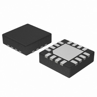
NB7L32M 2.5V/3.3V, 14GHz ÷2 Clock Divider w/CML Output and Internal Termination Description The NB7L32M is an integrated ÷2 divider with differential clock inputs and asynchronous reset. Differential clock inputs incorporate internal 50 W termination resistors and accept LVPECL (Positive ECL), ...
Page 2
VTCLK VTCLK Table 1. PIN DESCRIPTION Pin Name I/O 1 VTCLK − 2 CLK ECL, CML, LVDS Input 3 CLK ECL, CML, LVDS Input 4 VTCLK − − − 12, 13, V ...
Page 3
Table 2. ATTRIBUTES Internal Input Pulldown Resistor ESD Protection Moisture Sensitivity (Note 1) Flammability Rating Transistor Count Meets or exceeds JEDEC Spec EIA/JESD78 IC Latchup Test 1. For additional information, see Application Note AND8003/D. Table 3. MAXIMUM RATINGS Symbol Parameter ...
Page 4
Table 4. DC CHARACTERISTICS, CLOCK INPUTS, CML OUTPUTS T = −40°C to +85°C A Symbol I Power Supply Current (Note Output HIGH Voltage (Note Output LOW Voltage (Note Internal Output Termination ...
Page 5
Table 6. AC CHARACTERISTICS V Symbol Characteristic V Output Voltage Amplitude (@ V OUTPP (See Figures and 6) f Maximum Input Clock Frequency IN (See Figure Propagation Delay to PLH t Output Differential ...
Page 6
TIME (190 ps/div) Figure 3. Typical Output Waveform with GHz 2 400 mV INPP Room Temperature 357 mV, OUTPP ps ps, f ...
Page 7
Q Driver Device Q Figure 8. Typical Termination for Output Driver and Device Evaluation (See Application Note AND8073/D − Termination of CML Logic Devices.) CLK V th CLK V th Figure 9. Differential Input Driven Single−Ended ...
Page 8
All NB7L32M inputs can accept PECL, CML, and LVDS signal levels. The limitations for differential input signal (LVDS, PECL, or CML) are minimum input swing of 150 mV and the maximum input swing of 2500 mV. Within these conditions, the ...
Page 9
... V CC LVDS Driver V EE ORDERING INFORMATION Device NB7L32MMNG NB7L32MMNR2G †For information on tape and reel specifications, including part orientation and tape sizes, please refer to our Tape and Reel Packaging Specifications Brochure, BRD8011/D. APPLICATION INFORMATION VTD VTD Figure 16. LVDS to NB7L32M Interface Package QFN−16 (Pb− ...
Page 10
... 0.05 C NOTE 3 *For additional information on our Pb−Free strategy and soldering details, please download the ON Semiconductor Soldering and Mounting Techniques Reference Manual, SOLDERRM/D. 6,362,644. N. American Technical Support: 800−282−9855 Toll Free USA/Canada Europe, Middle East and Africa Technical Support: Phone: 421 33 790 2910 Japan Customer Focus Center Phone: 81− ...