FC100V5A POWER ONE, FC100V5A Datasheet - Page 12
FC100V5A
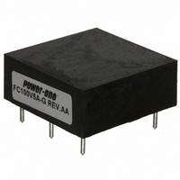
Manufacturer Part Number
FC100V5A
Description
FILTER 5 AMP PC MOUNT
Manufacturer
POWER ONE
Series
FCr
Datasheet
1.FC100V5A-G.pdf
(41 pages)
Specifications of FC100V5A
Filter Type
Power Line
Voltage - Rated
100V
Current
5A
Mounting Type
Through Hole
Termination Style
PCB Pins
Operating Temperature Min Deg. C
-40C
Operating Temperature Max Deg. C
85C
Rad Hardened
No
Lead Free Status / RoHS Status
Contains lead / RoHS non-compliant
Inductance
-
Lead Free Status / RoHS Status
Contains lead / RoHS non-compliant, Not Compliant
Other names
179-2178
Available stocks
Company
Part Number
Manufacturer
Quantity
Price

Part Number:
FC100V5A
Manufacturer:
POWER-O
Quantity:
20 000
Part Number:
FC100V5A
Quantity:
55


For additional information regarding layout and EMC,
refer to the Layout Considerations and EMI
Considerations Application notes.
The following bulleted items are considerations
regarding the external components for the typical
application shown in Fig. 5.
Input electrolytic capacitor C1. We recommend
Input capacitors C2, C3 are optional; they
MCD10059 Rev. 1.1, 21-Jan-10
1-2 µF/W for 48 V applications, and 2-4 µF/W for
24 V applications. This capacitor is needed to
ensure stability of converters in presence of their
negative input impedance characteristic. Note that
electrolytic capacitors at –40 ºC have 3-5 times
less capacitance than at room temperature, and
therefore it is good practice to check the power
system at worst case conditions from this point of
view, i.e. lowest ambient temperature, minimum
input voltage, and maximum load. If electrolytic
capacitors are restricted for use in the system,
please contact the factory.
decrease input ripple current and improve EMI.
One or two of the following ceramic chip
capacitors,
recommended:
–
–
TDK C4532X7R2A105, 1.0 µF, 100V - for
48 V applications
TDK C4532X7R1H475, 4.7 µF, 50V - for
24 V applications
as
required,
per
converter
F2410 & F4810, 0-45V/0-80V, 10 Amps, SMT Mount
F & FC Series DC-DC Converter Input Filters
are
Page 12 of 41
Common-mode capacitor (Y-cap) values and
their EMI attenuation effects depend on system
grounding and layout (they are not shown on Fig.
5). In EMI testing with the filter, ceramic
capacitors between input and output of the
converter (C4 – C7) were very helpful. Typical
values for the capacitor between Vin- and Vout-
are 3,300 pF – 5,100 pF, and for the capacitor
between Vin+ and Vout+, 0 to 3,300 pF.
If connection of capacitors between input and
output
restrictions, connect Y-capacitors only from each
input pin to system ground. The value of these
capacitors in this case is “the bigger the better”
(preferably 0.1 µF or larger). Voltage rating of
Y-capacitors depends on the system isolation
and safety requirements.
Output capacitors C8, C9 are optional to reduce
output ripple. Addition of one-two 47 µF ceramic
capacitors,
applications 3.3 V and below, significantly
decreases output ripple from 25-40 mV peak-to-
peak to 5-10 mV. Recommended capacitor for
these
C3225X5R0J476 from TDK.
UL testing was performed with a 12 Amps fuse
(R451012 from Littelfuse). Fuses larger than
12 Amps should not be used. Smaller value
fuses can be used as required for protection to a
lower power limit.
is
low
prohibited
for
voltage
example,
because
www.power-one.com
for
applications
low
of
voltage
system
is
Related parts for FC100V5A
Image
Part Number
Description
Manufacturer
Datasheet
Request
R

Part Number:
Description:
SWITCHING POWER SUPPLIES, SINGLE OUTPUT, 80 WATTS
Manufacturer:
POWER ONE
Datasheet:
Part Number:
Description:
HAS SERIES - 30 WATT
Manufacturer:
POWER ONE
Datasheet:
Part Number:
Description:
SINGLE OUTPUT
Manufacturer:
POWER ONE
Datasheet:

Part Number:
Description:
BRS DC/DC converters(1.5 WATT)
Manufacturer:
Power-One
Datasheet:
Part Number:
Description:
3...15 Watt DC-DC Converter
Manufacturer:
Power-One
Datasheet:
Part Number:
Description:
HBS SERIES - 100 WATT
Manufacturer:
Power-One
Datasheet:
Part Number:
Description:
3...15 Watt DC-DC Converter
Manufacturer:
Power-One
Datasheet:
Part Number:
Description:
BUS DC/DC converters(3 WATT)
Manufacturer:
Power-One
Datasheet:
Part Number:
Description:
HES SERIES 150 WATT
Manufacturer:
Power-One
Datasheet:
Part Number:
Description:
1.25 WATT
Manufacturer:
Power-One
Datasheet: