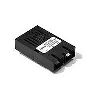
HFCT-5205C Avago Technologies US Inc., HFCT-5205C Datasheet - Page 5

HFCT-5205C
Manufacturer Part Number
HFCT-5205C
Description
Manufacturer
Avago Technologies US Inc.
Datasheet
1.HFCT-5205C.pdf
(10 pages)
Specifications of HFCT-5205C
Optical Fiber Type
TX/RX
Data Transfer Rate
155Mbps
Optical Rise Time
2ns
Optical Fall Time
2ns
Operating Temperature Classification
Industrial
Peak Wavelength
1360nm
Operating Supply Voltage (min)
4.75V
Operating Supply Voltage (typ)
5V
Operating Supply Voltage (max)
5.25V
Output Current
30mA
Operating Temp Range
-40C to 85C
Mounting
Through Hole
Pin Count
9
Lead Free Status / RoHS Status
Compliant
Figure 4 - Recommended Circuit Schematic
Regulatory Compliance
5
TERMINATE
AT THE
DEVICE
INPUTS
Feature
Electrostatic Discharge
(ESD) to the Electrical
Pins
Electrostatic Discharge
(ESD) to the Duplex SC
Receptacle
Electromagnetic Interfer-
ence (EMI)
Immunity
Eye Safety
R6
NO INTERNAL
CONNECTION
V
EER
1
RD
R5
V
RD
CC
C6
2
RD
R7
RD
3
R8
SD
Test Method
MIL-STD-883C
Method 3015.4
Variation of IEC 801-2
FCC Class B
CENELEC EN55022 Class B
VCCI Class 1
Variation of IEC 801-3
FDA CDRH 21-CFR 1040Class I CDRH Accession Number: 9521220-26
IEC 825 Issue 1 1993:11Class 1
CENELEC EN60825 Class 1
SD
R10
4
C1
(CISPR 22A)
TOP VIEW
C3
TRANSCEIVER
C7
AT V
V
V
R9
CCR
5
cc
L1 L2
FILTER
V
cc
CC
PINS
V
CCT
6
C8
C4
C2
TD
7
TD
NO INTERNAL
CONNECTION
TERMINATION
TRANSCEIVER
R1
TD
R2
8
INPUTS
V
CC
AT
C5
V
R3
9
EET
R4
Performance
Class 1 (>1 kV) - Human Body Model
Products of this type, typically, withstand at least 25 kV
without damage when the Duplex SC Connector Recep-
tacle is contacted by a Human Body Model probe.
Typically provide a 17 dB margin to the noted standard
limits up to 6 GHz, when tested in a GTEM cell with the
transceiver mounted to a circuit card with a chassis enclo-
sure.
Typically show no measurable effect from a 10 V/m field
swept from 27 MHz to 1 GHz applied to the transceiver
without a chassis enclosure.
TUV Bauart License: 933/510018/02
TD
NOTES:
THE SPLIT-LOAD TERMINATIONS FOR ECL SIGNALS
NEED TO BE LOCATED AT THE INPUT OF DEVICES
RECEIVING THOSE ECL SIGNALS. RECOMMEND
4-LAYER PRINTED CIRCUIT BOARD WITH 50 W
MICROSTRIP SIGNAL PATHS BE USED.
R1 = R4 = R6 = R8 = R10 = 130 W
R2 = R3 = R5 = R7 = R9 = 82 W
C1 = C2 = 10 µF (see Figure 2)
C3 = C4 = C7 = C8 = 100 nF
C5 = C6 = 0.1 µF
L1 = L2 = 3.3 µH COIL OR FERRITE INDUCTOR.


