AFBR732B Avago Technologies US Inc., AFBR732B Datasheet
AFBR732B
Specifications of AFBR732B


Related parts for AFBR732B


AFBR732B Summary of contents
Page 1
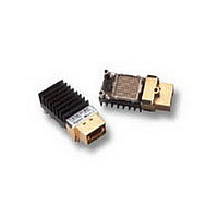
AFBR-732BWZ/BEWZ/BEHWZ and AFBR-742BZ/BEZ/BEHZ Ultra Short Link Pluggable Parallel Fiber Optic Modules, Transmitter and Receiver Data Sheet Description The AFBR-732BWZ transmitter and AFBR-742BZ receiver are high performance fiber optic modules for parallel optical data communication applications. These 12- channel devices, operating ...
Page 2
Design Summary: Design for low-cost, high-volume manufacturing Avago’s parallel optics solution combines twelve 2.5 Gb/s channels into discrete transmitter and receiver modules providing a maximum aggregate data rate of 30 Gb/s. Moreover, these modules employ a heat sink for thermal ...
Page 3
DIN+ INPUT STAGE SHIFTER 12 DIN- 4 SERIAL CONTROLLER CONTROL I/O* Figure 1. Transmitter block diagram(each channel). * TX_EN, TX_DIS, RESET-, FAULT- PIN TRANS- IMPEDANCE PRE-AMPLIFIER Figure 2. Receiver block diagram (each channel). 3 SHUT AMPLIFIER DOWN LEVEL DRIVER ...
Page 4
Electromagnetic Interference (EMI) Many equipment designs using these high-data-rate modules will be required to meet the requirements of the FCC in the United States, CENELEC in Europe and VCCI in Japan. These modules, with their shielded design, perform to the ...
Page 5
Absolute Maximum Ratings Parameter Storage Temperature (non-operating) Case Temperature (operating) Supply Voltage Data/Control Signal Input Voltage Transmitter Differential Data Input Voltage Output Current (dc) Relative Humidity (non-condensing) RH Notes: 1. Absolute Maximum Ratings are those values beyond which damage ...
Page 6
Electrical Characteristics Transmitter Electrical Characteristics ( °C to +80 ° 3.3 V ± 5%, Typical Parameter Supply Current Power Dissipation Differential Input Impedance FAULT Assert Time RESET Assert Time RESET De-assert Time Transmit ...
Page 7
Receiver Electrical Characteristics ( °C to +80 ° 3.3 V ± 5%, Typical Parameter Supply Current Power Dissipation Differential Output Impedance Data Output Differential Peak-to-Peak Volt- age Swing Inter-channel Skew Differential Data Output ...
Page 8
Optical Characteristics Transmitter Optical Characteristics ( °C to +80 ° 3.3 V ± 5%, Typical Parameter Output Optical Power Output Optical Power – Off State Optical Modulation Amplitude Center Wavelength Spectral Width – ...
Page 9
Receiver Optical Characteristics ( °C to +80 ° 3.3 V ± 5%, Typical Parameter Input Optical Power Sensitivity (OMA) Input Optical Power Saturation (OMA) Operating Center Wavelength Stressed Receiver Sensitivity (OMA) Stressed Receiver ...
Page 10
Regulatory Compliance Table Feature Test Method Electrostatic Discharge JEDEC Human Body Model (HBM) (ESD) to the Electrical (JESD22-A114-B) Pads JEDEC Machine Model (MM) Electrostatic Discharge Variation of IEC 61000-4-2 (ESD) to the Connector Receptacle Electromagnetic FCC Part 15 CENELEC EN55022 ...
Page 11
Table 1. Transmitter Module Pad Description Symbol Functional Description V Transmitter Signal Common. All voltages are referenced to this potential unless otherwise indi- EE cated. Directly connect these pads to transmitter signal ground plane Transmitter Power Supply. Use ...
Page 12
TRANSMITTER MODULE PAD ASSIGNMENT (TOWARD MTP® CONNECTOR DNC DNC DNC DNC DNC DNC DNC CCT CCT EE 4 DNC V V DIN3+ CCT CCT 5 DNC ...
Page 13
RECEIVER MODULE PAD ASSIGNMENT (TOWARD MTP® CONNECTOR DNC DNC DNC DNC DNC DOUT4- DOUT5+ CCR CCR EE 4 DNC V V DOUT3- ...
Page 14
Case Temperature Measurement Point Figure 3. Case temperature measurement. (label and heatsink removed for clarity) 25.0 20.0 15.0 10.0 5.0 0.0 0 0.5 Air Velocity (m/s) Figure 4. Case to Ambient thermal resistance (C/W) versus air velocity (sea level) 14 ...
Page 15
AFBR-742BZ V CCR V CCR V CCR V CCR V CCR V CCR V CCR V CCR NOTE DEFINED BY 3.135 < < 3.465 VOLTS AND THE POWER SUPPLY FILTER HAS < ...
Page 16
AFBR-732BWZ C = 100 nF R 100 100 nF AFBR-742BZ D OUT (+) C = 100 nF D OUT (– 100 nF NOTE: AC COUPLING CAPACITORS SHOULD BE USED TO CONNECT DATA OUTPUTS TO DATA ...
Page 17
MIN KEEP-OUT ∅ 0 ∅ 2.69 ± 0.05 HOLES FOR #2 SCREW ∅ 0.1 A B-C 18.42 MIN. 50 KEEP-OUT AREA FOR MPO CONNECTOR NOTE: The host electrical connector attached ...
Page 18
V CCR Figure 10. Rx data output equivalent circuit. V > 2 ~60 ms ~6.5 ms SHUTDOWN TX OUT 0 ~4 OUT 1 SHUTDOWN ~4.6 ms SHUTDOWN TX ...
Page 19
RESET FAULT > 100 ns (Ton) ~55 ms ~4.2 ms SHUTDOWN TX OUT 0 ~4 OUT 1 ~4 OUT 2 TX OUT 11 ~5 µs (Toff) Figure 14. Transmitter RESET timing diagram. TX_EN ~5 µs (Toff) ...
Page 20
Module Outline Notes: 1. Module supplied with port process plug. 2. Module mass approximately 20 grams. Figure 16. Package outline for AFBR-732BWZ and AFBR-742BZ (dimensions in mm). 20 ...
Page 21
Notes: 1. Module supplied with port process plug. 2. Module mass approximately 20 grams. Figure 17. Package Outline for AFBR-732BEWZ and AFBR-742BEZ (dimensions in mm) 21 ...
Page 22
Figure 18. Host Frontplate Layout (dimensions in mm) For product information and a complete list of distributors, please go to our web site: Avago, Avago Technologies, and the A logo are trademarks of Avago Technologies Limited in the United States ...