SCDQ5544R OSRAM Opto Semiconductors Inc, SCDQ5544R Datasheet - Page 11
SCDQ5544R
Manufacturer Part Number
SCDQ5544R
Description
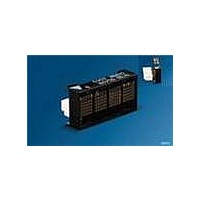
LED Displays 5x5 Hi-Eff Green 0.126 4-CHARACTER
Manufacturer
OSRAM Opto Semiconductors Inc
Series
Intelligent Display®r
Datasheet
1.SCDQ5542P.pdf
(16 pages)
Specifications of SCDQ5544R
Display Type
Dot Matrix
Emitting Color
Hi-Eff. Green
Number Of Digits
4
Digit Size (in)
.134in
Viewing Area Height (mm)
3.4mm
Viewing Area Length (mm)
3.4mm
Package Type
Panel
Operating Supply Voltage (min)
4.5V
Operating Supply Voltage (typ)
5V
Operating Supply Voltage (max)
5.5V
Operating Temperature Classification
Industrial
Operating Temp Range
-40C to 85C
Mounting
Through Hole
Pin Count
5
Total Thickness (mm)
5.08mm
Opto Display Type
Panel
Pattern Type
Dot Matrix
Millicandela Rating
6.4mcd
Size / Dimension
0.78" L x 0.40" W x 0.20" H (19.91mm x 10.16mm x 5.08mm)
Color
Green
Configuration
5 x 5
Character Size
0.134 in
Illumination Color
High Efficiency Green
Wavelength
568 nm
Maximum Operating Temperature
+ 85 C
Minimum Operating Temperature
- 40 C
Luminous Intensity
6.4 mcd
Viewing Area (w X H)
3.4 mm x 3.4 mm
Lead Free Status / RoHS Status
Compliant
Voltage - Forward (vf) Typ
-
Internal Connection
-
Lead Free Status / Rohs Status
Details
Other names
Q68100A1474R


ESD Protection
The input protection structure of the SCDQ554XX provides signifi-
cant protection against ESD damage. It is capable of withstanding
discharges greater than 2.0 kV. Take all the standard precautions,
normal for CMOS components. These include properly grounding
personnel, tools, tables, and transport carriers that come in con-
tact with unshielded parts. If these conditions are not, or cannot be
met, keep the leads of the device shorted together or the parts in
anti-static packaging.
Soldering Considerations
The SCDQ554XX can be hand soldered with SN63 solder using a
grounded iron set to 260°C.
Wave soldering is also possible following these conditions: Pre-
heat that does not exceed 93°C on the solder side of the PC board
or a package surface temperature of 85°C. Water soluble organic
acid flux (except carboxylic acid) or resin-based RMA flux without
alcohol can be used.
Wave temperature of 245°C ± 5°C with a dwell between 1.5 s to
3.0 s. Exposure to the wave should not exceed temperatures
above 260°C for five seconds at 1.59 mm (0.063") below the seat-
ing plane. The packages should not be immersed in the wave.
The SCDQ554XR connects to an external connector receptacle
which may be soldered before inserting the SCDQ554XR Display.
In this way, only the connector is subject to the user’s soldering
process. The Molex 52418-0510 receptacle called out in the prod-
uct drawing can be used in solder reflow processes. See Molex for
specifications.
Post Solder Cleaning Procedures
The least offensive cleaning solution is hot D.I. water (60°C) for
less than 15 minutes. Addition of mild saponifiers is acceptable.
Do not use commercial dishwasher detergents.
For faster cleaning, solvents may be used. Exercise care in choos-
ing solvents as some may chemically attack the nylon package.
For further information refer to Appnotes 18 and 19 at
www.osram-os.com or in the current Short Form Catalogue. See
Appnote 19, Table 2, “Displays–Group 2”.
Optical Considerations
The 3.12 mm (0.123") high character of the SCDQ554XX gives
readability up to five feet. Proper filter selection enhances readabil-
ity over this distance.
Using filters emphasizes the contrast ratio between a lit LED and
the character background. This will increase the discrimination of
different characters. The only limitation is cost. Take into consider-
ation the ambient lighting environment for the best cost/benefit
ratio for filters.
Incandescent (with almost no green) or fluorescent (with almost no
red) lights do not have the flat spectral response of sunlight. Plas-
tic band-pass filters are an inexpensive and effective way to
strengthen contrast ratios. The SCDQ5542X is a super-red display
and should be matched with long wavelength pass filter in the
570 nm to 590 nm range. The SCDQ5541X/3X/4X should be
matched with a yellow-green band-pass filter that peaks at
565 nm. For displays of multiple colors, neutral density grey filters
offer the best compromise.
Additional contrast enhancement is gained by shading the dis-
plays. Plastic band-pass filters with built-in louvers offer the next
step up in contrast improvement. Plastic filters can be improved
further with anti-reflective coatings to reduce glare. The trade-off is
fuzzy characters. Mounting the filters close to the display reduces
2006-05-12
SCDQ5541P/Q/R, SCDQ5542P/Q/R, SCDQ5543P/Q/R, SCDQ5544P/Q/R
11
this effect. Take care not to overheat the plastic filter by allowing for
proper air flow.
Optimal filter enhancements are gained by using circular polarized,
anti-reflective, band-pass filters. The circular polarizing further
enhances contrast by reducing the light that travels through the fil-
ter and reflects back off the display to less than 1%.
Several filter manufacturers supply quality filter materials. Some of
them are: Panelgraphic Corporation, W. Caldwell, NJ; SGL Homa-
lite, Wilmington, DE; 3M Company, Visual Products Division, St.
Paul, MN; Polaroid Corporation, Polarizer Division, Cambridge,
MA; Marks Polarized Corporation, Deer Park, NY, Hoya Optics,
Inc., Fremont, CA.
One last note on mounting filters: recessing displays and bezel
assemblies is an inexpensive way to provide a shading effect in
overhead lighting situations. Several Bezel manufacturers are:
R.M.F. Products, Batavia, IL; Nobex Components, Griffith Plastic
Corp., Burlingame, CA; Photo Chemical Products of California,
Santa Monica, CA; I.E.E.-Atlas, Van Nuys, CA.
Related parts for SCDQ5544R
Image
Part Number
Description
Manufacturer
Datasheet
Request
R

Part Number:
Description:
Manufacturer:
OSRAM Opto Semiconductors Inc
Datasheet:

Part Number:
Description:
INTELLIGENT DISP 4CHAR 5X7 HERED
Manufacturer:
OSRAM Opto Semiconductors Inc
Datasheet:

Part Number:
Description:
DISPLAY 8DIGIT CERAMIC GREEN
Manufacturer:
OSRAM Opto Semiconductors Inc
Datasheet:

Part Number:
Description:
EMITTER IR 950NM 5MM SMD RADIAL
Manufacturer:
OSRAM Opto Semiconductors Inc
Datasheet:

Part Number:
Description:
LED TOPLED GREEN 570NM 2-PLCC
Manufacturer:
OSRAM Opto Semiconductors Inc
Datasheet:

Part Number:
Description:
INTERRUPTER RELFECT W/FILTR SMD
Manufacturer:
OSRAM Opto Semiconductors Inc
Datasheet:

Part Number:
Description:
LED Displays 5x7 Green 0.145 , 4-CHARACTER
Manufacturer:
OSRAM Opto Semiconductors Inc
Datasheet:
Part Number:
Description:
Q65110A4321_SIDELED PURE GREEN EOL150407
Manufacturer:
OSRAM Opto Semiconductors Inc
Datasheet:
Part Number:
Description:
Q65110A1202_RO DETECTOR 3/5MM_TR_RO
Manufacturer:
OSRAM Opto Semiconductors Inc
Datasheet:
Part Number:
Description:
INTELLIGENT DISP 4CHAR 5X7 HERED
Manufacturer:
OSRAM Opto Semiconductors Inc
Datasheet:
Part Number:
Description:
LED TOPLED GREEN 570NM 2-PLCC
Manufacturer:
OSRAM Opto Semiconductors Inc
Datasheet:

Part Number:
Description:
PHOTODIODE 900NM 3MM W/FILTER
Manufacturer:
OSRAM Opto Semiconductors Inc
Datasheet:

Part Number:
Description:
PHOTODIODE 850NM THRU-HOLE
Manufacturer:
OSRAM Opto Semiconductors Inc
Datasheet:

Part Number:
Description:
PHOTODIODE 880NM W/FILTER SMD
Manufacturer:
OSRAM Opto Semiconductors Inc
Datasheet: