SFECV10M7JA00-R0 Murata Electronics North America, SFECV10M7JA00-R0 Datasheet - Page 56
SFECV10M7JA00-R0
Manufacturer Part Number
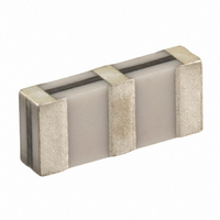
SFECV10M7JA00-R0
Description
FILTER 10.7MHZ 150KHZ BANDWIDTH
Manufacturer
Murata Electronics North America
Series
SFECVr
Specifications of SFECV10M7JA00-R0
Frequency
10.7MHz Center
Impedance
330 Ohm
Bandwidth
150kHz
Filter Type
FM
Insertion Loss
5.5dB
Package / Case
0.272" L x 0.114" W x 0.059" H (6.90mm x 2.90mm x 1.50mm)
Mounting Type
Surface Mount
Lead Free Status / RoHS Status
Lead free / RoHS Compliant
Other names
490-1230-2
SFECV10.7MJS-A-TC
SFECV10.7MJS-A-TC
Available stocks
Company
Part Number
Manufacturer
Quantity
Price
Company:

Part Number:
SFECV10M7JA00-R0
Manufacturer:
MURATA
Quantity:
148


16
!Note
• This PDF catalog is downloaded from the website of Murata Manufacturing co., ltd. Therefore, it’s specifications are subject to change or our products in it may be discontinued without advance notice. Please check with our
• This PDF catalog has only typical specifications because there is no space for detailed specifications. Therefore, please approve our product specifications or transact the approval sheet for product specifications before ordering.
sales representatives or product engineers before ordering.
!Note
SMD ceramic trap TPSKA_B is small and thin SMD trap
sealed with a metal cap. Recommended for LCD-TVs, and
small and thin tuners.
1. High attenuation and high performance group
2. Small and thin package
3. Reflow-solderable
54
TPSKA4M50B00-R3
TPSKA5M50B00-R3
TPSKA6M00B00-R3
TPSKA6M50B00-R3
For safety purposes, connect the output of filters to the IF amplifier through a D.C. blocking capacitor. Avoid applying a direct current to the output of ceramic filters.
The order quantity should be an integral multiple of the "Minimum Quantity" shown in the package page.
CERAFILr (Filters/Traps/Discriminators) for Audio/Visual Equipment
Ceramic Trap 4.5-6.5MHz Chip Type TPSKA Series
Features
delay time
Standard Land Pattern Dimensions
Frequency Characteristics
10
20
30
40
50
60
70
0
• Please read rating and !CAUTION (for storage, operating, rating, soldering, mounting and handling) in this catalog to prevent smoking and/or burning, etc.
• This catalog has only typical specifications because there is no space for detailed specifications. Therefore, please approve our product specifications or transact the approval sheet for product specifications before ordering.
4.0
Part Number
4.1
4.2
1.0
4.3
TPSKA4M50B00-R1
1.5
4.4
1.0
Frequency (MHz)
4.5
1.5
Nominal Center
Frequency (fn1)
1.0
4.6
(MHz)
4.500
5.500
6.000
6.500
4.7
(in mm)
4.8
4.9
5.0
Test Circuit
S.S.G.
Attenuation
10
20
30
40
50
60
70
0
35 min.
35 min.
35 min.
35 min.
(at fn1)
5.0
(dB)
Rg
5.1
5.2
50
Rg=50
R1=330
R2=1.0k
R1
5.3
TPSKA5M50B00-R1
0.6 0.2
(1)
2.5 0.2 2.5 0.2
5.4
Frequency (MHz)
8.5 0.2
7.9 0.2
(2)
L
5.5
1.0 0.1
(3)
Continued on the following page.
30dB Attenuation
5.6
BW (fn1)
1.3 0.2
0.3 0.1
1.3 0.2
0.5 0.1
50 min.
70 min.
70 min.
70 min.
R2
1.8 0.2
(kHz)
5.7
L=15 H
(1) : Input
(2) : Ground
(3) : Output
5.8
3.0 0.1
3.8 0.2
5.9
RF
Voltmeter
(in mm)
6.0
P50E.pdf
10.2.9
Related parts for SFECV10M7JA00-R0
Image
Part Number
Description
Manufacturer
Datasheet
Request
R

Part Number:
Description:
BUZZER PIEZO 25VP-P SMD
Manufacturer:
Murata Electronics North America

Part Number:
Description:
CAP 4-ARRAY 680PF 100V X7R 1206
Manufacturer:
Murata Electronics North America
Datasheet:
Part Number:
Description:
CAP 4-ARRAY 1000PF 100V X7R 1206
Manufacturer:
Murata Electronics North America
Datasheet:
Part Number:
Description:
CAP 4-ARRAY 1800PF 100V X7R 1206
Manufacturer:
Murata Electronics North America
Datasheet:
Part Number:
Description:
CAP 4-ARRAY 68000PF 16V X7R 1206
Manufacturer:
Murata Electronics North America
Datasheet:

Part Number:
Description:
CAP CER 1000PF 50V 10% X7R 0402
Manufacturer:
Murata Electronics North America
Datasheet:
Part Number:
Description:
CAP CER 10000PF 16V 10% X7R 0402
Manufacturer:
Murata Electronics North America
Datasheet:

Part Number:
Description:
CAP 5.5-25PF 2.5X3.2MM SMD
Manufacturer:
Murata Electronics North America
Datasheet:

Part Number:
Description:
CAP 4.5-20PF 2.5X3.2MM SMD
Manufacturer:
Murata Electronics North America
Datasheet:

Part Number:
Description:
CAP 5.0-20PF 3.2X4.5MM SMD RED
Manufacturer:
Murata Electronics North America
Datasheet:

Part Number:
Description:
CAP 2.0-6.0PF 3.2X4.5MM SMD BLU
Manufacturer:
Murata Electronics North America
Datasheet:

Part Number:
Description:
CAP 1.4-3.0PF 3.2X4.5MM SMD BRN
Manufacturer:
Murata Electronics North America
Datasheet:

Part Number:
Description:
CAP 3.0-10PF 3.2X4.5MM SMD WHT
Manufacturer:
Murata Electronics North America
Datasheet:

Part Number:
Description:
CAP 2.0-6.0PF 4X4.5MM TOPADJ BLU
Manufacturer:
Murata Electronics North America
Datasheet:

Part Number:
Description:
CAP 8.5-40PF 4X4.5MM TOPADJ YEL
Manufacturer:
Murata Electronics North America
Datasheet: