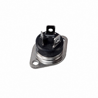
BTA40-800B STMicroelectronics, BTA40-800B Datasheet - Page 3

BTA40-800B
Manufacturer Part Number
BTA40-800B
Description
TRIAC 800V 40A RD-91
Manufacturer
STMicroelectronics
Specifications of BTA40-800B
Triac Type
Standard
Mounting Type
Chassis Mount
Configuration
Single
Current - Hold (ih) (max)
80mA
Voltage - Off State
800V
Current - Gate Trigger (igt) (max)
50mA
Current - Non Rep. Surge 50, 60hz (itsm)
400A, 420A
Current - On State (it (rms)) (max)
40A
Voltage - Gate Trigger (vgt) (max)
1.3V
Package / Case
RD91-3 (Insulated)
Current - On State (it (rms) (max)
40A
Current, Average Input
40 A
Current, Dc Gate-trigger
50 mA
Current, Dc Holding
80 mA (Max.)
Current, On-state, Rms, Maximum
40 A
Current, Surge, Non-repetitive Peak Forward
420 A for 60 Hz, 400 A for 50 Hz
Dissipation, Gate-power, Average
1 W
Package Type
RD91
Resistance, Thermal, Junction To Case
0.9 °C⁄W
Temperature, Operating, Maximum
125 °C
Temperature, Operating, Minimum
-40 °C
Thermal Resistance, Junction To Ambient
50 °C⁄W
Voltage, Dc Gate-trigger
1.3 V (Max.)
Lead Free Status / RoHS Status
Lead free / RoHS Compliant
Other names
497-2405
497-2405-5
497-2405
497-2405-5
497-2405
Available stocks
Company
Part Number
Manufacturer
Quantity
Price
Company:
Part Number:
BTA40-800B
Manufacturer:
WINBOND
Quantity:
21 000
Part Number:
BTA40-800B
Manufacturer:
ST
Quantity:
20 000
BTA40, BTA41, BTB41
Table 4.
1. Minimum I
2. for both polarities of A2 referenced to A1
Table 5.
Figure 1.
Figure 3.
Symbol
50
40
30
20
10
1.E+00
1.E-02
1.E-03
Symbol
0
1.E-01
V
V
R
I
I
R
R
DRM
RRM
t0
T
P(W)
0
d
th(j-c)
th(j-a)
(1)
(2)
(2)
1.E-03
K=[Z /R
5
GT
th
Static characteristics
Thermal resistance
Z
Maximum power dissipation versus
on-state rms current (full cycle)
Relative variation of thermal
impedance versus pulse duration
I
Threshold voltage
Dynamic resistance
V
th(j-c)
1.E-02
TM
is guaranted at 5% of I
th
DRM
Junction to case (AC)
Junction to ambient
10
]
= 60 A
= V
1.E-01
BTA / BTB41
15
Z
th(j-a)
RRM
I
T(RMS)
1.E+00
20
t (s)
p
t
p
(A)
= 380 µs
25
1.E+01
GT
max.
30
1.E+02
Test conditions
Test conditions
35
180°
Doc ID 7469 Rev 8
1.E+03
RD91 (insulated) / TOP3 insulated
TOP3
TOP3 / TOP3 insulated
40
Figure 2.
Figure 4.
T
T
T
T
T
j
j
j
400
100
45
40
35
30
25
20
15
10
j
j
10
5
0
= 125 °C
= 125 °C
= 125 °C
= 25 °C
= 25 °C
1
0
I
T(RMS)
0.5
I
TM
T =
j
R = 10 m
V = 0.85V
(A)
to
d
T max.
T max.
j
j
(A)
1.0
On-state rms current versus case
temperature (full cycle)
On-state characteristics (maximum
values)
25
1.5
T = 25°C
j
2.0
MAX.
MAX.
MAX.
MAX.
.
50
T (°C)
C
2.5
V
TM
(V)
3.0
75
Value
BTA40
BTA41
0.9
0.6
50
3.5
Value
1.55
0.85
Characteristics
10
5
5
4.0
100
BTB41
4.5
=180°
°C/W
°C/W
Unit
Unit
m
mA
µA
125
V
V
5.0
3/9


