5223957-1 TE Connectivity, 5223957-1 Datasheet - Page 48
5223957-1
Manufacturer Part Number
5223957-1
Description
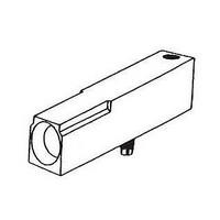
Connector Accessories Guide Module Zinc Alloy Die Cast Chromate Finish
Manufacturer
TE Connectivity
Type
Guide Moduler
Series
Z-PACKr
Datasheet
1.5223957-1.pdf
(52 pages)
Specifications of 5223957-1
Product Length (mm)
34.2mm
Product Depth (mm)
7.9mm
Product Height (mm)
13.7mm
Accessory Type
Guide Module
Rohs Compliant
Yes
Product Type
Female
Number Of Rows
1
Number Of Positions / Contacts
1
Mounting Angle
Right
Termination Style
Screw
Housing Material
Zinc Alloy
Contact Material
Stainless Steel
Mounting Style
PCB
Pcb Mounting Orientation
Right Angle
Keyed
No
Thread Size
4-40
Guide Module Material
Zinc Alloy Die Casting , Zamak 3
Guide Module Finish
Chromate Conversion
Rohs/elv Compliance
RoHS compliant, ELV compliant
Lead Free Solder Processes
Not relevant for lead free process
Rohs/elv Compliance History
Always was RoHS compliant
Lead Free Status / RoHS Status
Compliant
For Use With
Z-Pack 2 Mm HM, Z-Pack HS3, Z-Pack HM-Zd And Multi GIG RT2J
Lead Free Status / Rohs Status
Details


Right-Angle
Receptacle Assemblies
with Solder Leads and
Compliant Press-Fit Leads
Material and Finish
Housing — Liquid crystal polymer
Receptacle Contacts — Phosphor
bronze, mating surface plating conforms
to all testing specified for Telcordia
Uncontrolled Environment, with entire
contact underplated with 0.00127 min.
nickel. See customer drawing for spe-
cific lead plating.
Technical Documents
Product Specification
108-1441
Application Specification
114-1075
Instruction Sheets
408-6927
Catalog 1773096
Revised 2-10
www.tycoelectronics.com
Dimensions are in inches and
millimeters unless otherwise
specified. Values in brackets
are metric equivalents.
1.00
4.00
Power Connectors & Interconnection Systems
Z-PACK 2 mm Futurebus+ Power Modules
Reference specification 114-1075 for plated through hole requirements.
Note: All part numbers are RoHS compliant.
Number of
Positions
2.00 Typ.
Recommended PC Board Hole Layout
10
8
12.00 Typ.
per IPC-D-300, Type II, Class C
(Component Side)
3 Spaces at
2.00 = 6.00 Ref.
9.50
Dimensions are shown for
reference purposes only.
Specifications subject
to change.
(Point of Contact)
2.25 Max.
0.107 [2.73]
5536607-1
5223092-1
4 Row
20.45
2.05
Dia. Typ.
Drilled Hole
Solder Tail Length
+0.10
-0.00
Part Numbers
1.50
Dia. Typ.
(Drilled Hole)
0.139 [3.53]
5536613-1
5223093-1
+0.10
-0.00
USA: 1-800-522-6752
Canada: 1-905-470-4425
Mexico: 01-800-733-8926
C. America: 52-55-1106-0803
3.00 ±0.15
3 Spaces at
2.00 = 6.00
4.00
0.140 [3.56]
5536614-1
5536649-1
(Continued)
Press-Fit
2.05
Dia. Typ.
Drilled Hole
3.00±0.15
+0.10
-0.00
4.00 Typ.
Recommended PC Board Hole Layout
1.00
4.00
per IPC-D-300, Type II, Class C
1.50
Dia. Typ.
(Drilled Hole)
4 Spaces at
2.00 = 8.00 Ref.
+0.10
-0.00
9.50
(Component Side)
(Point of Contact)
South America: 55-11-2103-6000
Hong Kong: 852-2735-1628
Japan: 81-44-844-8013
UK: 44-(0)8002-67666
2.25 Max.
Industry Standard Flat Rock
Industry Standard Flat Rock
22.45
5 Row
6.00
Seating Tool
5 Spaces at
2.00 = 10.00 Ref.
4 Spaces at
2.00 = 8.00 Ref.
57
Related parts for 5223957-1
Image
Part Number
Description
Manufacturer
Datasheet
Request
R

Part Number:
Description:
Printers THERMAL PRINTER HS-SLEEVE MARKER
Manufacturer:
TE Connectivity


Part Number:
Description:
High Speed / Modular Connectors 30P HEADER ASSY
Manufacturer:
TE Connectivity
Datasheet:

Part Number:
Description:
High Speed / Modular Connectors REC 6X005P R/A LT B-PLANE HS3
Manufacturer:
TE Connectivity
Datasheet:


Part Number:
Description:
Manufacturer:
TE Connectivity
Datasheet:


Part Number:
Description:
Manufacturer:
TE Connectivity
Datasheet:

Part Number:
Description:
Manufacturer:
TE Connectivity
Datasheet:

Part Number:
Description:
Manufacturer:
TE Connectivity
Datasheet:


Part Number:
Description:
Manufacturer:
TE Connectivity
Datasheet: