XP0111M00L Panasonic - SSG, XP0111M00L Datasheet
XP0111M00L
Manufacturer Part Number
XP0111M00L
Description
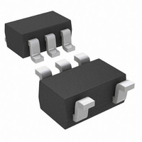
TRANS ARRAY PNP/PNP W/RES SMINI5
Manufacturer
Panasonic - SSG
Datasheet
1.XP0111M00L.pdf
(4 pages)
Specifications of XP0111M00L
Transistor Type
2 PNP - Pre-Biased (Dual)
Current - Collector (ic) (max)
100mA
Voltage - Collector Emitter Breakdown (max)
50V
Resistor - Base (r1) (ohms)
2.2K
Resistor - Emitter Base (r2) (ohms)
47K
Dc Current Gain (hfe) (min) @ Ic, Vce
80 @ 5mA, 10V
Vce Saturation (max) @ Ib, Ic
250mV @ 300µA, 10mA
Current - Collector Cutoff (max)
500nA
Frequency - Transition
80MHz
Power - Max
150mW
Mounting Type
Surface Mount
Package / Case
S-Mini 5P
Lead Free Status / RoHS Status
Lead free / RoHS Compliant
Other names
XP0111M00LTR


Composite Transistors
XP0111M
Silicon PNP epitaxial planar type
For digital circuits
■ Features
■ Basic Part Number
■ Absolute Maximum Ratings T
■ Electrical Characteristics T
Note) 1. Measuring methods are based on JAPANESE INDUSTRIAL STANDARD JIS C 7030 measuring methods for transistors.
Publication date: May 2009
• Two elements incorporated into one package
• Reduction of the mounting area and assembly cost by one half
• UNR211M × 2
Collector-base voltage (Emitter open)
Collector-emitter voltage (Base open)
Collector current
Total power dissipation
Junction temperature
Storage temperature
Collector-base voltage (Emitter open)
Collector-emitter voltage (Base open)
Collector-base cutoff current (Emitter open)
Collector-emitter cutoff current (Base open)
Emitter-base cutoff current (Collector open)
Forward current transfer ratio
h
Collector-emitter saturation voltage
Output voltage high-level
Output voltage low-level
Input resistance
Resistance ratio
Transition frequency
(Emitter-coupled transistors with built-in resistor)
FE
Ratio
2. * : Ratio between 2 elements
*
Parameter
Parameter
This product complies with the RoHS Directive (EU 2002/95/EC).
a
Symbol
= 25°C ± 3°C
V
V
Symbol
h
T
V
R
P
CBO
I
T
V
V
FE(Small
CEO
/Large)
a
I
I
I
V
stg
V
C
1
CE(sat)
T
h
CBO
j
CEO
EBO
R
f
= 25°C
CBO
CEO
FE
OH
OL
/ R
T
1
2
−55 to +150
Rating
I
I
V
V
V
V
V
I
V
V
V
C
C
C
−100
−50
−50
150
150
CB
CE
EB
CE
CE
CC
CC
CB
= −10 µA, I
= −2 mA, I
= −10 mA, I
SJJ00134CED
= −50 V, I
= −6 V, I
= −10 V, I
= −10 V, I
= −50 V, I
= −5 V, V
= −5 V, V
= −10 V, I
Conditions
Unit
mW
B
C
mA
°C
°C
E
V
V
B
B
B
B
C
C
E
E
= 0
= 0
= 0
= − 0.5 V, R
= −2.5 V, R
= 0
= 0
= −5 mA
= −5 mA
= − 0.3 mA
= 1 mA, f = 200 MHz
L
■ Package
■ Marking Symbol: EK
■ Internal Connection
L
• Code
• Pin Name
= 1 kΩ
= 1 kΩ
SMini5-G1
1: Base (Tr1)
2: Emitter
3: Base (Tr2)
−30%
−4.9
0.50
Min
−50
−50
80
Tr1
5
1
0.047
0.99
Typ
2.2
80
2
4: Collector (Tr2)
5: Collector (Tr1)
− 0.25
+30%
− 0.1
− 0.5
− 0.2
− 0.2
Tr2
Max
4
3
MHz
Unit
mA
µA
µA
kΩ
V
V
V
V
V
1
Related parts for XP0111M00L
Image
Part Number
Description
Manufacturer
Datasheet
Request
R

Part Number:
Description:
IC CIRCUIT PROTECTOR 1A SMINI 2P
Manufacturer:
Panasonic - SSG
Datasheet:
Part Number:
Description:
IC CIRCUIT PROTECTR .7A SMINI 2P
Manufacturer:
Panasonic - SSG
Datasheet:

Part Number:
Description:
IC CIRCUIT PROTCTR 1.2A SMINI 2P
Manufacturer:
Panasonic - SSG
Datasheet:

Part Number:
Description:
IC CIRCUIT PROTECTR 1.2A SNMP 2P
Manufacturer:
Panasonic - SSG
Datasheet:
Part Number:
Description:
IC CIRCUIT PROTECTOR 1A SNMP 2P
Manufacturer:
Panasonic - SSG
Datasheet:
Part Number:
Description:
IC CIRCUIT PROTECTR 1.8A SNMP 2P
Manufacturer:
Panasonic - SSG
Datasheet:
Part Number:
Description:
IC CIRCUIT PROTECTR 2.3A SNMP 2P
Manufacturer:
Panasonic - SSG
Datasheet:

Part Number:
Description:
DIODE ZENER DUAL 6.2V SSMINI-3
Manufacturer:
Panasonic - SSG
Datasheet:
Part Number:
Description:
DIODE ZENER DUAL 6.8V SSSMINI3P
Manufacturer:
Panasonic - SSG
Datasheet:

Part Number:
Description:
DIODE ZENER QUAD 12V SSMINI-5
Manufacturer:
Panasonic - SSG
Datasheet:
Part Number:
Description:
DIODE ZENER 15V 150MW S-MINI 2P
Manufacturer:
Panasonic - SSG
Datasheet:


Part Number:
Description:
DIODE ZENER 9.1V 150MW SSMINI-2
Manufacturer:
Panasonic - SSG
Datasheet:
Part Number:
Description:
DIODE ZENER 15V 150MW SSMINI-2
Manufacturer:
Panasonic - SSG
Datasheet: