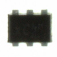
UPA863TD-A CEL, UPA863TD-A Datasheet

UPA863TD-A
Specifications of UPA863TD-A
Related parts for UPA863TD-A
UPA863TD-A Summary of contents
Page 1
NPN SILICON RF TRANSISTOR (WITH 2 DIFFERENT ELEMENTS 6-PIN LEAD-LESS MINIMOLD FEATURES • Low voltage operation • 2 different built-in transistors (2SC5436, 2SC5800) Q1: Built-in high gain transistor f = 12.0 GHz TYP., ⏐S ⏐ T 21e Q2: ...
Page 2
ABSOLUTE MAXIMUM RATINGS (T Parameter Symbol Collector to Base Voltage V Collector to Emitter Voltage V Emitter to Base Voltage Total Power ...
Page 3
ELECTRICAL CHARACTERISTICS (T (1) Q1 Parameter Symbol Collector Cut-off Current I CBO Emitter Cut-off Current I EBO DC Current Gain h FE Gain Bandwidth Product f Insertion Power Gain ⏐ ...
Page 4
TYPICAL CHARACTERISTICS (Unless otherwise specified, T TOTAL POWER DISSIPATION vs. AMBIENT TEMPERATURE 300 Mounted on Glass Epoxy PCB 2 (1.08 cm × 1.0 mm (t) ) 250 2 Elements in total 210 200 190 Q2 150 100 ...
Page 5
Q 1 COLLECTOR CURRENT vs. BASE TO EMITTER VOLTAGE 100 0.1 0.01 0.001 0.0001 0.6 0 Base to Emitter Voltage V BE COLLECTOR CURRENT vs. BASE ...
Page 6
Q 1 COLLECTOR CURRENT vs. COLLECTOR TO EMITTER VOLTAGE step B 400 A μ Collector to Emitter Voltage V 6 COLLECTOR CURRENT vs. COLLECTOR TO EMITTER ...
Page 7
CURRENT GAIN vs. COLLECTOR CURRENT 1 000 V 100 Collector Current I (mA CURRENT GAIN vs. COLLECTOR CURRENT 1 000 V 100 ...
Page 8
Q 1 GAIN BANDWIDTH PRODUCT vs. COLLECTOR CURRENT GHz Collector Current I (mA) C GAIN BANDWIDTH PRODUCT vs. COLLECTOR CURRENT ...
Page 9
Q 1 INSERTION POWER GAIN, MAG, MSG vs. FREQUENCY MSG MAG 21e 5 0 0.1 1 Frequency f (GHz) INSERTION POWER ...
Page 10
INSERTION POWER GAIN, MAG, MSG vs. FREQUENCY 35 30 MSG 0.1 Data Sheet P15686EJ1V0DS μ μ μ PA863TD MAG ...
Page 11
Q 1 INSERTION POWER GAIN, MAG, MSG vs. COLLECTOR CURRENT 20 MSG MAG 21e GHz Collector Current I (mA) C INSERTION POWER ...
Page 12
Q 1 INSERTION POWER GAIN, MAG, MSG vs. COLLECTOR CURRENT 20 MSG 21e GHz Collector Current I C INSERTION POWER GAIN, MAG, ...
Page 13
Q 1 NOISE FIGURE, ASSOCIATED GAIN vs. COLLECTOR CURRENT GHz Collector Current I (mA) C NOISE FIGURE, ASSOCIATED GAIN vs. COLLECTOR ...
Page 14
Q 1 NOISE FIGURE, ASSOCIATED GAIN vs. COLLECTOR CURRENT GHz Collector Current I (mA) C NOISE FIGURE, ASSOCIATED GAIN vs. COLLECTOR ...
Page 15
S-PARAMETERS mA Ω Frequency S 11 (GHz) MAG. ANG. (deg.) 0.1 0.953 −9.4 0.2 0.949 −16.5 0.3 0.929 −24.4 0.4 0.911 −33.0 0.5 0.878 −41.3 0.6 ...
Page 16
mA Ω Frequency S 11 (GHz) MAG. ANG. (deg.) 0.1 0.800 −19.3 0.2 0.747 −37.9 0.3 0.689 −54.3 0.4 0.627 −69.9 0.5 0.564 −84.1 0.6 0.519 −96.3 ...
Page 17
mA Ω Frequency S 11 (GHz) MAG. ANG. (deg.) 0.1 0.653 −29.6 0.2 0.584 −56.8 0.3 0.519 −77.0 0.4 0.461 −96.1 0.5 0.423 −111.1 0.6 0.397 −124.0 ...
Page 18
mA Ω Frequency S 11 (GHz) MAG. ANG. (deg.) 0.1 0.970 −8.2 0.2 0.955 −15.0 0.3 0.935 −22.1 0.4 0.921 −30.1 0.5 0.889 −37.6 0.6 0.861 −45.3 ...
Page 19
mA Ω Frequency S 11 (GHz) MAG. ANG. (deg.) 0.1 0.820 −17.5 0.2 0.769 −33.1 0.3 0.708 −47.8 0.4 0.645 −61.6 0.5 0.582 −74.6 0.6 0.529 −86.0 ...
Page 20
mA Ω Frequency S 11 (GHz) MAG. ANG. (deg.) 0.1 0.679 −26.0 0.2 0.607 −48.0 0.3 0.538 −66.7 0.4 0.471 −83.9 0.5 0.417 −97.6 0.6 0.381 −110.5 ...
Page 21
S-PARAMETERS mA Ω Frequency S 11 (GHz) MAG. ANG. (deg.) 0.1 0.965 −24.1 0.2 0.935 −46.4 0.3 0.904 −66.0 0.4 0.876 −83.9 0.5 0.848 −99.0 0.6 ...
Page 22
mA Ω Frequency S 11 (GHz) MAG. ANG. (deg.) 0.1 0.830 −44.6 0.2 0.756 −79.1 0.3 0.711 −103.5 0.4 0.680 −121.8 0.5 0.660 −134.7 0.6 0.651 −144.9 ...
Page 23
mA Ω Frequency S 11 (GHz) MAG. ANG. (deg.) 0.1 0.708 −63.2 0.2 0.647 −104.2 0.3 0.617 −126.0 0.4 0.605 −141.2 0.5 0.600 −151.8 0.6 0.600 −159.5 ...
Page 24
mA Ω Frequency S 11 (GHz) MAG. ANG. (deg.) 0.1 0.963 −22.6 0.2 0.934 −45.4 0.3 0.911 −64.6 0.4 0.878 −82.4 0.5 0.847 −97.3 0.6 0.826 −110.3 ...
Page 25
mA Ω Frequency S 11 (GHz) MAG. ANG. (deg.) 0.1 0.847 −42.1 0.2 0.767 −75.3 0.3 0.712 −99.6 0.4 0.676 −117.9 0.5 0.657 −131.3 0.6 0.644 −141.8 ...
Page 26
mA Ω Frequency S 11 (GHz) MAG. ANG. (deg.) 0.1 0.717 −59.4 0.2 0.644 −97.6 0.3 0.611 −120.6 0.4 0.594 −137.0 0.5 0.585 −148.1 0.6 0.583 −156.2 ...
Page 27
PACKAGE DIMENSIONS 6-PIN LEAD-LESS MINIMOLD (UNIT: mm) 1.0±0.05 +0.07 0.8 –0. PIN CONNECTIONS Data Sheet P15686EJ1V0DS μ μ μ PA863TD (Top View Collector (Q1) 2. ...
Page 28
The information in this document is current as of July, 2001. The information is subject to change without notice. For actual design-in, refer to the latest publications of NEC's data sheets or data books, etc., for the most up-to-date ...
Page 29
... C AS numbers and other limited information ma y not be availab le for release event shall CEL’s liability ari s ing out of such information e x cee d the total purch ase price of the CEL part ( s) at issue s old by CEL to customer on an annual basis. ...


