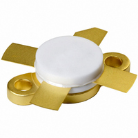
BLF147,112 NXP Semiconductors, BLF147,112 Datasheet - Page 9

BLF147,112
Manufacturer Part Number
BLF147,112
Description
TRANSISTOR RF DMOS SOT121B
Manufacturer
NXP Semiconductors
Datasheet
1.BLF147112.pdf
(15 pages)
Specifications of BLF147,112
Package / Case
SOT-121B
Transistor Type
N-Channel
Frequency
108MHz
Gain
14dB
Voltage - Rated
65V
Current Rating
25A
Voltage - Test
28V
Power - Output
150W
Minimum Operating Temperature
- 65 C
Mounting Style
SMD/SMT
Resistance Drain-source Rds (on)
0.15 Ohm @ 10 V
Transistor Polarity
N-Channel
Configuration
Single Dual Source
Drain-source Breakdown Voltage
65 V
Gate-source Breakdown Voltage
+/- 20 V
Continuous Drain Current
25 A
Power Dissipation
220000 mW
Maximum Operating Temperature
+ 200 C
Application
HF/VHF
Channel Type
N
Channel Mode
Enhancement
Drain Source Voltage (max)
65V
Output Power (max)
150W
Power Gain (typ)@vds
19@28VdB
Frequency (max)
108MHz
Package Type
CRFM
Pin Count
4
Forward Transconductance (typ)
7.5S
Drain Source Resistance (max)
150@10Vmohm
Input Capacitance (typ)@vds
450@28VpF
Output Capacitance (typ)@vds
360@28VpF
Reverse Capacitance (typ)
55@28VpF
Operating Temp Range
-65C to 200C
Drain Efficiency (typ)
40%
Mounting
Screw
Mode Of Operation
SSB Class-AB
Number Of Elements
1
Power Dissipation (max)
220000mW
Vswr (max)
50
Screening Level
Military
Lead Free Status / RoHS Status
Lead free / RoHS Compliant
Noise Figure
-
Current - Test
-
Lead Free Status / Rohs Status
Lead free / RoHS Compliant
Other names
568-2385
933930000112
BLF147
BLF147
933930000112
BLF147
BLF147
NXP Semiconductors
List of components (see Fig 13).
Notes
1. American Technical Ceramics (ATC) capacitor, type 100B or other capacitor of the same quality.
2. The striplines are on a double copper-clad printed circuit board, with PTFE fibre-glass dielectric (
C1, C3, C13, C14
C2, C8, C9
C4, C5
C6
C7
C10
C11, C12
C15
L1
L2, L3
L4
L5, L6
L7
R1, R2
R3
R4
R5
VHF power MOS transistor
COMPONENT
thickness 1.6 mm.
film dielectric trimmer
multilayer ceramic chip capacitor;
note 1
multilayer ceramic chip capacitor
multilayer ceramic chip capacitors in
parallel
electrolytic capacitor
multilayer ceramic chip capacitor;
note 1
multilayer ceramic chip capacitor;
note 1
multilayer ceramic chip capacitor;
note 1
6 turns enamelled 0.7 mm copper
wire
stripline; note 2
4 turns enamelled 1.5 mm copper
wire
grade 3B Ferroxcube wideband HF
choke
3 turns enamelled 2.2 mm copper
wire
1 W metal film resistor
0.4 W metal film resistor
0.4 W metal film resistor
1 W metal film resistor
DESCRIPTION
Rev. 06 - 5 December 2006
7 to 100 pF
75 pF
100 nF
3
2.2 F, 63 V
100 pF
150 pF
240 pF
145 nH
41.1
148 nH
79 nH
19.6
10 k
1 M
10
VALUE
100 nF
length 5 mm;
int. dia. 6 mm;
leads 2
length 13
length 8 mm;
int. dia. 10 mm;
leads 2
length 8 mm;
int. dia. 8 mm;
leads 2
DIMENSIONS
5 mm
5 mm
5 mm
6 mm
2222 809 07015
2222 852 47104
2222 852 47104
4312 020 36642
2322 153 51969
2322 151 71003
2322 151 71005
2322 153 51009
Product specification
CATALOGUE NO.
r
= 2.2),
BLF147
9 of 15


