BAR 14-1 E6327 Infineon Technologies, BAR 14-1 E6327 Datasheet
BAR 14-1 E6327
Specifications of BAR 14-1 E6327
BAR14-1E6327INTR
BAR141E6327XT
SP000010164


Related parts for BAR 14-1 E6327


BAR 14-1 E6327 Summary of contents
Page 1
Silicon PIN Diode RF switch, RF attenuator for frequencies above 10 MHz Low distortion faktor Long-term stability of electrical characteristics Pb-free (RoHS compliant) package Qualified according AEC Q101 BAR14-1 BAR15-1 Type BAR14-1 BAR15-1 BAR16-1 BAR61 Maximum Ratings ...
Page 2
Electrical Characteristics at T Parameter DC Characteristics Reverse current 100 V R Forward voltage I = 100 Characteristics Diode capacitance 100 MHz R V ...
Page 3
... Forward current 25°C A BAR 14-1...16 -40 ˚ ˚C 85 ˚C 150 ˚ 0.0 0 Forward resistance 100MHz EHD07067 MHz 100 MHz Forward current I F BAR14-1, BAR15-1, BAR16-1 EHD07065 160 mA 120 100 1 BAR1.../BAR61... = ( BAR 14-1...16 105 120 ° 2007-04-19 EHD07066 150 T S ...
Page 4
Application circuit for attenuation networks with diode BAR61 Input 238 1 k BAR 5 BAR1.../BAR61... +12 V ...
Page 5
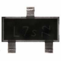
Package Outline Foot Print Marking Layout (Example) Standard Packing Reel ø180 mm = 3.000 Pieces/Reel Reel ø330 mm = 10.000 Pieces/Reel Package SOT143 2.9 ±0 0.2 +0.1 0.8 -0.05 +0.1 0.4 -0.05 0.25 B ...
Page 6
Package Outline Foot Print Marking Layout (Example) Standard Packing Reel ø180 mm = 3.000 Pieces/Reel Reel ø330 mm = 10.000 Pieces/Reel Pin 1 Package SOT23 2.9 ±0 +0.1 0.4 -0.05 C 0.95 1.9 0.25 B ...
Page 7
... For information on the types in question please contact your nearest Infineon Technologies Office. Infineon Technologies Components may only be used in life-support devices or systems with the express written approval of Infineon Technologies failure of such components can reasonably be expected to cause the failure of that life-support device or system affect the safety or effectiveness of that device or system ...