PSMN010-55D,118 NXP Semiconductors, PSMN010-55D,118 Datasheet
PSMN010-55D,118
Specifications of PSMN010-55D,118
PSMN010-55D /T3
PSMN010-55D /T3


Related parts for PSMN010-55D,118


PSMN010-55D,118 Summary of contents
Page 1
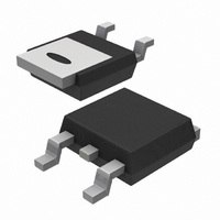
... Applications:- • d.c. to d.c. converters • switched mode power supplies The PSMN010-55D is supplied in the SOT428 (Dpak) surface mounting package. LIMITING VALUES Limiting values in accordance with the Absolute Maximum System (IEC 134) SYMBOL PARAMETER ...
Page 2
... 175˚ 1 Resistive load Measured tab to centre of die Measured from source lead to source bond pad MHz Product specification PSMN010-55D MIN. MAX. UNIT - 264 MIN. TYP. MAX. UNIT - - 1 MIN. TYP. MAX. UNIT -55˚ 1 175˚C 0 -55˚ 2.3 - 7.4 10 0.02 ...
Page 3
... SYMBOL PARAMETER I Continuous source current S (body diode) I Pulsed source current (body SM diode) V Diode forward voltage SD t Reverse recovery time rr Q Reverse recovery charge rr October 1999 transistor CONDITIONS -dI /dt = 100 Product specification PSMN010-55D MIN. TYP. MAX. UNIT - - 240 A - 0. Rev 1.200 ...
Page 4
... Fig.6. Typical on-state resistance Product specification PSMN010-55D Transient thermal impedance, Zth j-mb (K/ 0.5 0.2 0.1 0.05 0. single pulse T 1E-05 1E-04 1E-03 1E-02 1E-01 Pulse width, tp (s) Fig.4. Transient thermal impedance. ...
Page 5
... I 10000 1000 100 100 120 140 160 180 Fig.12. Typical capacitances f f Product specification PSMN010-55D Threshold Voltage, VGS(TO) (V) maximum typical minimum 100 120 140 160 180 Junction Temperature, Tj (C) Fig.10. Gate threshold voltage. = f(T ); conditions mA Drain current, ID (A) minimum ...
Page 6
... V; parameter T F SDS GS October 1999 transistor Maximum Avalanche Current, I 100 10 VDD = 100 0.001 Fig.15. Maximum permissible non-repetitive avalanche current ( 0.8 0.9 1 1.1 1 Product specification PSMN010-55D ( prior to avalanche = 150 C 0.01 0.1 1 Avalanche time, t (ms versus avalanche time (t AS unclamped inductive load Rev 1.200 ...
Page 7
... REFERENCES IEC JEDEC EIAJ 7 Product specification PSMN010-55D SOT428 max. max. min. 2.95 0.7 10.4 0.2 0.2 0.5 9.6 2.55 0.5 EUROPEAN ISSUE DATE ...
Page 8
... Philips Semiconductors N-channel logic level TrenchMOS MOUNTING INSTRUCTIONS Dimensions in mm October 1999 transistor 7.0 7.0 2.15 2.5 4.57 Fig.17. SOT428 : soldering pattern for surface mounting . 8 Product specification PSMN010-55D 1.5 Rev 1.200 ...
Page 9
... Philips customers using or selling these products for use in such applications their own risk and agree to fully indemnify Philips for any damages resulting from such improper use or sale. October 1999 transistor 9 Product specification PSMN010-55D Rev 1.200 ...