4140 Cinch Connectors, 4140 Datasheet - Page 119
4140
Manufacturer Part Number
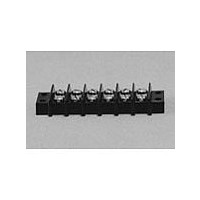
4140
Description
Terminal Block,8 Contacts,0.375 Pitch
Manufacturer
Cinch Connectors
Type
Barrier Stripr
Datasheet
1.4140.pdf
(282 pages)
Specifications of 4140
Number Of Contacts
4POS
Number Of Contact Rows
2
Termination Method
Screw
Mounting Style
Panel
Contact Pitch (mm)
9.53mm
Current Rating (max)
15A
Operating Temp Range
-48C to 148C
Housing Material
Phenolic
Body Orientation
Straight
Operating Voltage (max)
250VAC
Product Height (mm)
28.58mm
Product Length (mm)
54.78mm
Wire Gauge
16
Lead Free Status / RoHS Status
Compliant
Available stocks
Company
Part Number
Manufacturer
Quantity
Price

Part Number:
4140-52
Manufacturer:
PEREGRINE
Quantity:
20 000
Company:
Part Number:
414002-2
Manufacturer:
TE
Quantity:
20 000
Company:
Part Number:
414026-2
Manufacturer:
BOURNS
Quantity:
20


D-subminiature Metal Shell
Overmold Kits
D*A and HTD Series
Shield Covers: Steel (stamped) with tin/lead finish
Ferrule: Brass
Call Toll Free: 1 (800) 323-9612
Dimensions
Overmold Shielding Kits
Positions
15 Plug
15 Socket
25 Plug
25 Socket
37 Plug
37 Socket
9 Plug
9 Socket
Cinch overmold kits enable you to overmold the connector of the cable assembly for less
material and process cost (versus a metal backshell), improved appearance, and improved
shielding of the connector to help meet RFI/EMI requirements.
An Overmold Kit catalog number consists of:
-
-
-
You will also need to order the following:
-
-
-
-
All specifications on the connector portion of the overmold kit can be found on pages 4-16 thru
4-17 for HPD 1.5 density and pages 4-20 thru 4-21 for D*A series.
D*A or HTD Crimp and Poke connector.
Inside shielding cover.
Outside shielding cover.
Crimp and Poke stamped contacts must be ordered separately on page 4-22 for D*A
and page 4-18 for HTD connectors.
Ferrules are required, but must be ordered separately according to the size necessary to
accommodate the wire. See page 4-25.
Termination tooling is required to crimp the wires on the connector.
A hand tool and appropriate crimping die are required for crimping the ferrule.
0.270
0.285
0.270
0.285
0.275
0.285
0.275
0.285
in
C
6.86
7.24
6.86
7.24
6.99
7.24
6.99
7.24
mm
0.705 17.91
0.705 17.91
1.050 26.67
1.050 26.67
1.590 40.39
1.590 40.39
2.240 56.90
2.240 56.90
in
D
mm
4-24
1.320 33.53
1.320 33.53
1.320 33.53
1.320 33.53
1.320 33.53
1.320 33.53
1.620 41.15
1.620 41.15
in
E
mm
0.520 13.21
0.520 13.21
0.520 13.21
0.520 13.21
0.520 13.21
0.520 13.21
0.750 19.05
0.750 19.05
in
F
mm
Deg.
75°
75°
58°
58°
40°
40°
32°
32°
G
0.440
0.440
0.440
0.440
0.440
0.440
0.520
0.520
in
H
11.18
11.18
11.18
11.18
11.18
11.18
13.21
13.21
mm
Related parts for 4140
Image
Part Number
Description
Manufacturer
Datasheet
Request
R

Part Number:
Description:
Standard Card Edge Connectors CINCH BLK CARD GUIDE
Manufacturer:
Cinch Connectors

Part Number:
Description:
TERMINAL BLOCK JUMPER TYPE F
Manufacturer:
Cinch Connectors
Datasheet:
Part Number:
Description:
D-Subminiature Connectors MCHNED PIN 20-24AWG
Manufacturer:
Cinch Connectors
Datasheet:
Part Number:
Description:
Terminal Block,4 Contacts,0.44 Pitch
Manufacturer:
Cinch Connectors
Datasheet: