STGP19NC60WD STMicroelectronics, STGP19NC60WD Datasheet - Page 5
STGP19NC60WD
Manufacturer Part Number
STGP19NC60WD
Description
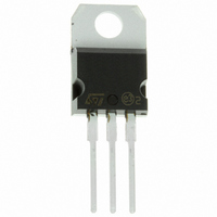
IGBT N-CHAN 600V 40A TO-220
Manufacturer
STMicroelectronics
Series
PowerMESH™r
Datasheet
1.STGP19NC60WD.pdf
(15 pages)
Specifications of STGP19NC60WD
Voltage - Collector Emitter Breakdown (max)
600V
Vce(on) (max) @ Vge, Ic
2.5V @ 15V, 12A
Current - Collector (ic) (max)
40A
Power - Max
125W
Input Type
Standard
Mounting Type
Through Hole
Package / Case
TO-220-3 (Straight Leads)
Channel Type
N
Configuration
Single
Collector-emitter Voltage
600V
Collector Current (dc) (max)
40A
Gate To Emitter Voltage (max)
±20V
Package Type
TO-220
Pin Count
3 +Tab
Mounting
Through Hole
Operating Temperature (max)
150C
Operating Temperature Classification
Military
Transistor Type
IGBT
Dc Collector Current
40A
Collector Emitter Voltage Vces
2.5V
Power Dissipation Pd
125W
Collector Emitter Voltage V(br)ceo
600V
Operating Temperature Range
-55°C To +150°C
Rohs Compliant
Yes
Lead Free Status / RoHS Status
Lead free / RoHS Compliant
Igbt Type
-
Lead Free Status / Rohs Status
Compliant
Other names
497-6027-5
Available stocks
Company
Part Number
Manufacturer
Quantity
Price
Company:

Part Number:
STGP19NC60WD
Manufacturer:
ST
Quantity:
12 500


STGP19NC60WD - STGW19NC60WD
Table 5.
Table 6.
1. Eon is the turn-on losses when a typical diode is used in the test circuit in
2. Turn-off losses include also the tail of the collector current
Symbol
(di/dt)
(di/dt)
Symbol
t
t
E
E
E
E
t
t
t
t
r
r
in a package with a co-pak diode, the co-pack diode is used as external diode. IGBTs & Diode are at the
same temperature (25°C and 125°C)
d
d
d(on)
d(on)
(V
(V
E
E
on
off
on
off
(
(
t
t
t
t
off
off
r
r
f
f
ts
ts
off
off
(1)
(2)
(1)
(2)
on
on
)
)
)
)
Turn-on delay time
Current rise time
Turn-on current slope
Turn-on delay time
Current rise time
Turn-on current slope
Off voltage rise time
Turn-off delay time
Current fall time
Off voltage rise time
Turn-off delay time
Current fall time
Turn-on switching losses
Turn-off switching losses
Total switching losses
Turn-on switching losses
Turn-off switching losses
Total switching losses
Switching on/off (inductive load)
Switching energy (inductive load)
Parameter
Parameter
V
R
Figure 17
V
R
Tj = 125°C
Figure 17
V
R
Figure 17
V
R
Tj = 125°C
Figure 17
V
R
Figure 17
V
R
Tj = 125°C
Figure 17
CC
CC
G
G
CC
CC
CC
CC
G
G
G
G
= 10Ω , V
= 10Ω , V
= 10Ω , V
= 10Ω , V
= 10Ω , V
= 10Ω , V
= 390V, I
= 390V, I
= 390V, I
= 390V, I
= 390V, I
= 390V, I
Test conditions
Test conditions
GE
GE
GE
GE
GE
GE
C
C
C
C
C
C
= 15V,
= 15V,
= 15V,
= 15V,
= 15V,
= 15V,
= 12A
= 12A
= 12A
= 12A
= 12A
= 12A
Figure 15
Electrical characteristics
Min.
Min.
If the IGBT is offered
1600
1400
Typ.
Typ.
127
125
206
161
255
416
25
25
22
90
43
47
77
81
7
8
Max.
Max.
A/µs
A/µs
Unit
Unit
ns
ns
ns
ns
ns
ns
ns
ns
ns
ns
µJ
µJ
µJ
µJ
µJ
µJ
5/15
Related parts for STGP19NC60WD
Image
Part Number
Description
Manufacturer
Datasheet
Request
R

Part Number:
Description:
STMicroelectronics [RIPPLE-CARRY BINARY COUNTER/DIVIDERS]
Manufacturer:
STMicroelectronics
Datasheet:
Part Number:
Description:
STMicroelectronics [LIQUID-CRYSTAL DISPLAY DRIVERS]
Manufacturer:
STMicroelectronics
Datasheet:

Part Number:
Description:
BOARD EVAL FOR MEMS SENSORS
Manufacturer:
STMicroelectronics
Datasheet:
Part Number:
Description:
NPN TRANSISTOR POWER MODULE
Manufacturer:
STMicroelectronics
Datasheet:
Part Number:
Description:
TURBOSWITCH ULTRA-FAST HIGH VOLTAGE DIODE
Manufacturer:
STMicroelectronics
Datasheet:
Part Number:
Description:
Manufacturer:
STMicroelectronics
Datasheet:
Part Number:
Description:
DIODE / SCR MODULE
Manufacturer:
STMicroelectronics
Datasheet:
Part Number:
Description:
DIODE / SCR MODULE
Manufacturer:
STMicroelectronics
Datasheet:
Part Number:
Description:
Search -----> STE16N100
Manufacturer:
STMicroelectronics
Datasheet:
Part Number:
Description:
Search ---> STE53NA50
Manufacturer:
STMicroelectronics
Datasheet:
Part Number:
Description:
NPN Transistor Power Module
Manufacturer:
STMicroelectronics
Datasheet:
Part Number:
Description:
DIODE / SCR MODULE
Manufacturer:
STMicroelectronics
Datasheet: