IRG4PC40UPBF International Rectifier, IRG4PC40UPBF Datasheet

IGBT UFAST 600V 40A TO247AC

IRG4PC40UPBF

Manufacturer Part Number
IRG4PC40UPBF
Description
IGBT UFAST 600V 40A TO247AC
Manufacturer
International Rectifier
Type
Ultrafastr
Datasheets

Specifications of IRG4PC40UPBF

Voltage - Collector Emitter Breakdown (max)
600V
Vce(on) (max) @ Vge, Ic
2.1V @ 15V, 20A
Current - Collector (ic) (max)
40A
Power - Max
160W
Input Type
Standard
Mounting Type
Through Hole
Package / Case
TO-247-3 (Straight Leads), TO-247AC
Channel Type
N
Configuration
Single
Collector-emitter Voltage
600V
Collector Current (dc) (max)
40A
Gate To Emitter Voltage (max)
±20V
Package Type
TO-247AC
Pin Count
3 +Tab
Mounting
Through Hole
Operating Temperature (max)
150C
Operating Temperature Classification
Military
Capacitance, Gate
2100 pF
Current, Collector
40 A
Energy Rating
15 mJ
Polarity
N-Channel
Power Dissipation
160 W
Resistance, Thermal, Junction To Case
0.77 °C/W
Speed, Switching
8 to 40 kHz (Hard Switching), >200 kHz (Resonant Mode)
Transistor Type
NPN
Voltage, Collector To Emitter Shorted
600 V
Voltage, Collector To Emitter, Saturation
2.15 V
Dc Collector Current
40A
Collector Emitter Voltage Vces
600V
Power Dissipation Pd
160W
Collector Emitter Voltage V(br)ceo
600V
Operating Temperature Range
-55°C To +150°C
Rohs Compliant
Yes
Lead Free Status / RoHS Status
Lead free / RoHS Compliant
Igbt Type
-
Lead Free Status / Rohs Status
Compliant
Other names
*IRG4PC40UPBF
INSULATED GATE BIPOLAR TRANSISTOR
Benefits
Thermal Resistance
Features
• Generation 4 IGBT's offer highest efficiency available
• IGBT's optimized for specified application conditions
• Designed to be a "drop-in" replacement for equivalent
Absolute Maximum Ratings
• UltraFast: Optimized for high operating
• Generation 4 IGBT design provides tighter
• Industry standard TO-247AC package
• Lead-Free
V
I
I
I
I
V
E
P
P
T
T
R
R
R
Wt
C
C
CM
LM
Generation 3
kHz in resonant mode
parameter distribution and higher efficiency than
J
ARV
STG
CES
GE
D
D
industry-standard Generation 3 IR IGBT's
θJC
θCS
θJA
frequencies 8-40 kHz in hard switching, >200
@ T
@ T
@ T
@ T
C
C
C
C
= 25°C
= 100°C
= 25°C
= 100°C
Collector-to-Emitter Voltage
Continuous Collector Current
Pulsed Collector Current Q
Clamped Inductive Load Current R
Gate-to-Emitter Voltage
Reverse Voltage Avalanche Energy S
Maximum Power Dissipation
Operating Junction and
Storage Temperature Range
Soldering Temperature, for 10 sec.
Mounting torque, 6-32 or M3 screw.
Junction-to-Case
Case-to-Sink, flat, greased surface
Junction-to-Ambient, typical socket mount
Weight
Parameter
Parameter
G
n-channel
------
------
------
------
Min.
300 (0.063 in. (1.6mm) from case)
IRG4PC40UPbF
E
C
10 lbf•in (1.1N•m)
-55 to +150
TO-247AC
UltraFast Speed IGBT
Max.
6 (0.21)
600
160
160
±20
160
40
20
15
65
Typ.
------
------
0.24
V
@V
CE(on) typ.
V
GE
CES
= 15V, I
Max.
------
------
0.77
40
PD-95184
= 600V
= 1.72V
C
= 20A
Units
g (oz)
Units
°C/W
mJ
W
°C
V
A
V
1

Related parts for IRG4PC40UPBF

IRG4PC40UPBF Summary of contents

Page 1

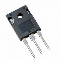
... Storage Temperature Range STG Soldering Temperature, for 10 sec. Mounting torque, 6- screw. Thermal Resistance Parameter R Junction-to-Case θJC R Case-to-Sink, flat, greased surface θCS R Junction-to-Ambient, typical socket mount θJA Wt Weight IRG4PC40UPbF UltraFast Speed IGBT C V CES V CE(on) typ 15V n-channel TO-247AC Max. 600 40 20 ...

Page 2

... IRG4PC40UPbF Electrical Characteristics @ T Parameter V Collector-to-Emitter Breakdown Voltage (BR)CES Emitter-to-Collector Breakdown Voltage T V (BR)ECS Temperature Coeff. of Breakdown Voltage ---- ∆V /∆T (BR)CES J V Collector-to-Emitter Saturation Voltage CE(on) V Gate Threshold Voltage GE(th) ∆V /∆T Temperature Coeff. of Threshold Voltage ---- GE(th Forward Transconductance Zero Gate Voltage Collector Current ...

Page 3

... IRG4PC40UPbF TO-247AC Package Outline Dimensions are shown in millimeters (inches) TO-247AC Part Marking Information EXAMPLE: T HIS IS AN IRFPE30 WIT EMBLY LOT CODE 5657 AS S EMBLE 35, 2000 EMBLY LINE "H" Note: "P" in assembly line position indicates "Lead-Free" 8 INT ERNAT IONAL RECT IFIE R IRFPE30 ...

Related keywords