84LS-AB2-112-N Grayhill Inc, 84LS-AB2-112-N Datasheet - Page 2
84LS-AB2-112-N
Manufacturer Part Number
84LS-AB2-112-N
Description
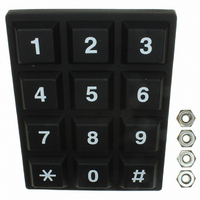
Pad Switch,SPST,Number Of Positions:12,PC TAIL Terminal
Manufacturer
Grayhill Inc
Series
84LSr
Datasheet
1.84LS-AB2-112-N.pdf
(3 pages)
Specifications of 84LS-AB2-112-N
Switch Type
Snap Dome
Number Of Keys
12
Matrix (columns X Rows)
3 x 4
Output Type
Matrix
Key Type
Rubber Overlay
Legend
Telephone Format
Interchangeable Legends
No
Illumination
Non-Illuminated
Seal Rating
IP67
Lead Free Status / RoHS Status
Lead free / RoHS Compliant
Other names
84LS-AB2-112-N
GH7449
GH7449


DIMENSIONS
CODE AND TRUTH TABLES
SPECIFICATIONS
Rating Criteria
Rating at 24 Vdc: ≤ 10 milliamps resistive
Contact Bounce: 4 milliseconds maximum at
make; 10 milliseconds, at break
Contact Resistance: MOS, TTL, and DTL
compatible. (10 ohms maximum)
Operating Temperature: -55°C to 85°C
Grayhill, Inc. • 561 Hillgrove Avenue • LaGrange, Illinois
4x4 Keyboard
The chart indicates the relationship of the terminal pins to each key switch.
The dot indicates a closed switch. Terminals are identified on the keyboard.
.750 (19,05) 3 EQ. SPS.
TOL. NON-ACCUM.
(78,74 ± 0,51)
3.100 ± .020
4 Button Keypads
.750 (19,05) 3 EQ. SPS.
.455 (11,56) SQ.
PRINTABLE AREA
TOL. NON-ACCUM.
1x4
.425 (10,80)
1
2
3
4
A B C D E
•
TERMINAL
LOCATION
CODES
•
PINS
(10,80)
.425
•
In inches (and millimeters)
•
•
•
•
•
13
1
5
9
(78,74 ± 0,51)
3.100 ± .020
3x4
10
14
SWITCH POSITION
IDENTIFICATION
2
6
10
11
12
1
2
3
4
5
6
7
8
9
C B A G F E D E C B F D A N K H M L J G
•
•
•
•
11
15
3
7
•
•
•
•
Matrix
•
•
•
•
12
16
4
8
•
•
•
12 Button Keypads
•
•
•
(12,45)
•
•
•
.490
SQ.
TERMINAL LOCATION
•
•
•
•
Life Expectancy: 3 million operations/button
Insulation Resistance:
Operating Features
Pre-Travel: .030 inches minimum
Operating Force: 20 ± 4 ounces
Humidity: 0 to 98% (no condensation)
Minimum Push Out Force Per Pin: 5 pounds
CODES
•
Single Pole/Common Bus
•
(0,64 ± 0,05) SQ.
60525-5997 • USA • Phone: 708-354-1040 • Fax: 708-354-2820 • www.grayhill.com
•
.025 ± .002
TERMINAL
•
.357 (9,07)
.207 (5,26)
.368 ± .015
(9,35 ± 0,38)
.267 ± .015
(6,78 ± 0,38)
PINS
•
•
•
(2,54)
•
.100
TYP.
(19,69)
•
.775
.100 (2,54) REF.
•
.310
(7,87)
2.120
(53,85)
PIN HEADER
(19,05)
TERMINAL
•
.750
•
•
•
•
•
•
•
•
•
•
•
•
Matrix Output
1,000 megohms
.490 (12,45)
1.500
4x4
(38,1)
10
11
12
13
14
15
16
1
2
3
4
5
6
7
8
9
F
E
D
B
C
A
G
H
A B C D E F G H D B A C H F E G K M L J P R Q N S
•
•
•
•
.098 (2,49) REF.
TERMINAL
PIN HEADER
•
•
•
•
TERMINAL PIN
IDENTIFICATION
•
•
•
•
Matrix
•
•
•
•
Standard Keypads
(28,58)
1.125
•
•
•
•
#6-32 MTG
STUD
6 PLACES
.425
(10,80)
LABEL
•
•
•
•
(57,15)
2.250
16 Button Keypads
•
•
•
•
Materials and Finishes
Terminal Pins: Copper alloy CDA 725
PC Board: FR-4 glass cloth epoxy
Dome Retainer/Rear Seal Sheet: Polyester
Mounting Studs: Phosphor bronze
Optional Hex Nut: Stainless steel, passivated
Optional EMI Shield: Aluminum foil
Keypad: Silicone rubber
•
•
•
•
TERMINAL LOCATION
•
(2,54)
2.120 (53,85)
.100
TYP.
.310 (7,87)
•
(20,32)
.100 (2,54) REF.
.800
•
Single Pole/Common Bus
CODES
PIN HEADER
(19,05)
TERMINAL
•
Single Pole/Common Bus
.750
•
•
•
.490 (12,45)
•
1.500
(38,1)
•
•
A
B
C
D
E
F
G
H
J
K
L
M
N
P
Q
R
S
.098 (2,49) REF.
TERMINAL
PIN HEADER
•
•
TERMINAL PIN
IDENTIFICATION
•
•
(28,58)
1.125
•
#6-32 MTG
STUD
6 PLACES
LABEL
.425
(10,80)
•
(57,15)
2.250
•
•
•
•
•
•
•
•
•
•
•
•
•
•
•
•
Keypads
15
Related parts for 84LS-AB2-112-N
Image
Part Number
Description
Manufacturer
Datasheet
Request
R

Part Number:
Description:
Pad Switch,SPST,Number Of Positions:12,PC TAIL Terminal
Manufacturer:
Grayhill Inc
Datasheet:

Part Number:
Description:
Pad Switch,SPST,Number Of Positions:12,PC TAIL Terminal
Manufacturer:
Grayhill Inc
Datasheet:
Part Number:
Description:
Pad Switch,SPST,Number Of Positions:12,PC TAIL Terminal
Manufacturer:
Grayhill Inc

Part Number:
Description:
Pad Switch,SPST,Number Of Positions:16,PC TAIL Terminal
Manufacturer:
Grayhill Inc
Datasheet:
Part Number:
Description:
Encoder; 32pos; custom switching; sealed; continous rotation;
Manufacturer:
Grayhill Inc
Part Number:
Description:
50EPT90-01-1-04N-C SINGLE DECK ROTARY 0.5(12.7mm)DIA,200mA,Continuous
Manufacturer:
Grayhill Inc
Part Number:
Description:
Rotary Switch seal adj.stop 36� 1deck 1pol/deck 56BSD36-01PAJN -bulk
Manufacturer:
Grayhill Inc
Part Number:
Description:
Rotary Switch, Screwdriver slot shaft, shaft/panel seal, PC mount, 30°
Manufacturer:
Grayhill Inc
Part Number:
Description:
Encoder MODIFIED SPECIAL VERSION OF GRH'S 60A18-4-040C
Manufacturer:
Grayhill Inc
Part Number:
Description:
GRAYHILL,SERIES 71,ROTARY SWITCH,1/8 SHAFT,30DEGREE,DECK,1 POLE/DECK,12POSITION/POLE,NON-SHORTING,CONTINUOUS .
Manufacturer:
Grayhill Inc
Part Number:
Description:
Keypad Legend, INC, Standard Font, White On Black
Manufacturer:
Grayhill Inc

Part Number:
Description:
SWITCH DIP EXTENDED UNSEAL 4POS
Manufacturer:
Grayhill Inc
Datasheet: