ADNS-5000 Avago Technologies US Inc., ADNS-5000 Datasheet
ADNS-5000
Specifications of ADNS-5000


Related parts for ADNS-5000


ADNS-5000 Summary of contents
Page 1
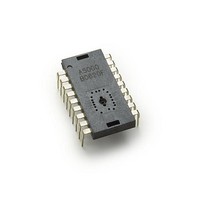
... ADNS-5000 Optical Mouse Sensor Data Sheet Description The ADNS-5000 is a one-chip USB optical mouse sensor for implementing a non-mechanical tracking engine for computer mice based on optical navigation technology that measures changes in position by optically acquiring sequential surface images (frames) and mathemati- cally determining the direction and magnitude of move- ment ...
Page 2
... Theory of Operation The ADNS-5000 is based on Optical Navigation Technol- ogy. It contains an Image Acquisition System (IAS), a Digital Signal Processor (DSP) and USB stream output. The IAS acquires microscopic surface images via the lens and illumination system provided by the ADNS-5100 Round Lens or ADNS-5100-001 Trim Lens, ADNS-5200, and HLMP-ED80-XX000 ...
Page 3
Figure 2. Package outline drawing CAUTION advised that normal static precautions be taken in handling and assembly of this component to prevent damage and/or degradation which may be induced by ESD. 3 ...
Page 4
... Figure 3. Recommended PCB mechanical cutouts and spacing (Top view) Figure 4. 2D assembly drawing of ADNS-5000 4 Note: The recommended pin hole dimension of the sen- sor is 0.7 mm. Shown with ADNS-5100, ADNS-5200 and HLMP-ED80- XX000 Avago Technologies provides an IGES file drawing de- scribing the base plate molding features for lens and ...
Page 5
... The components interlock as they are mounted onto defined features on the base plate. The ADNS-5000 sensor is designed for mounting on a through hole PCB, looking down. The aperture stop and features on the package align it to the lens (See figure 3). The ADNS-5100 Round lens provides optics for the imag- ing of the surface as well as illumination of the surface at the optimum angle ...
Page 6
... Install mouse top case. Figure 7. Typical Application 6 Design considerations for improving ESD Performance The table below shows typical values assuming base plate construction per the Avago Technologies supplied IGES file and ADNS-5100 Round lens. Typical distance A5100 Creepage 40.5mm Clearance 32.6mm A5100-001 17 ...
Page 7
Typical Application +3.3V Vdd 5V C1, C2 0.1uF C4 = 4.7uF VDD5 VDD3 GND C3 REG0 LED_ Vdd 5V GND GND +3.3V 1.5k XYLED NAV LED OSC IN USB D- ...
Page 8
Absolute Maximum Ratings Parameter Symbol Storage Temperature T S Operating Temperature T A Lead Solder Temp Supply Voltage V DD ESD Input Voltage V IN Input Voltage V IN Input Voltage V IN Input Short Circuit Voltage V SC Recommended ...
Page 9
AC Electrical Specifications Electrical Characteristics over recommended operating conditions. Typical values at 25 °C, V Parameter Symbol Power up delay T PUP Debounce delay on T DBB button inputs Mechanical Z-Wheel Transient Supply Current I DDT Input Capacitance C OSC_IN ...
Page 10
USB Timing Specifications Timing Specifications over recommended operating conditions. Parameter Symbol D+/D- Transition rise time T LR D+/D- Transition rise time T LR D+/D- Transition fall time T LF D+/D- Transition fall time T LF Rise and Fall time matching ...
Page 11
CRS Figure 10. Data Signal Rise and Fall Times V (min (min (max (max) OL GND Figure 11. Data Signal Voltage Levels 0.0 ...
Page 12
T PERIOD Differential Data Lines T DJR Consecutive Transitions Figure 13. Receiver Jitter Tolerance T PERIOD Crossover Point Differential Data Lines Differential Data to SE0 Skew PERIOD Figure 14. Differential to EOP Transition Skew ...
Page 13
... Z-H [2,3] Figure 16. Typical Resolution vs. Z Notes: 1. The ADNS-5000 is designed for optimal performance when used with the HLMP-ED80-XX000 (Red LED 639nm distance from Lens Reference Plane to Surface. 3. DOF = Depth of Field 13 Minimum Typical Maximum Units 7.2 mA 6.2 ...
Page 14
Configuration after Power up (Data Values) State from Figure 9-1 of USB spec: Signal Function Powered or Default Address or Configured B1 Hi-Z if tied to VDD3 else pullup active B2 Hi-Z if tied to VDD3 else pullup active B3 ...
Page 15
... V xxxx POSITIVE X Figure 18. Directions are for a complete mouse, with the ADNS-5100 lens XY LED x The peak current values are 59ohm and the part meets the IEC 825-1 eye safety regulations. Buttons The minimum time between button presses is T tons B1 through B3 are connected to a Schmidt trigger input with 100 uA current sources pulling volts during normal, sleep and USB suspend modes ...
Page 16
... The last two bytes in a command shown as “nn 00” specify the 16-bit data size in the order of “LowByte HighByte. ” For example a two-byte data size would be specifed as “02 00. ” ADNS-5000 will not provide more bytes than the number requested in the command, but it will only supply maximum of 8 bytes at a time ...
Page 17
USB COMMAND DETAILS ___________________________________________________________________________________________ USB_RESET D+/D- low for an extended period USB Spec: A device may reset after seeing an SE0 for more than 18.6 uS, and definitely after 10mS. Notes: After power up and prior to Reset, the device ...
Page 18
Get_Status_Endpt1 Returns xx[0] = Halt xx[7: (Reserved) Default: Stall (undefined in USB Spec) Addressed: Stall Configured: Accept Notes: Use Set_Feature_Endpt1/Clear_Feature_Endpt1 to set/clear Halt bit. ...
Page 19
Get_Desc_Confi Returns ...
Page 20
With Z-Wheel ...
Page 21
Get_Desc_String xx= 00 Language String 02 Product String Returns “unicode string” String descriptor length These values are determined by jumper configuration on page 14: For xx=00: 04 ...
Page 22
Get_Desc_HID_Report Returns: This returns a report descriptor that describes how many buttons and data. These values are determined by jumper configuration see table on page 14: Without Z-wheel: 05 ...
Page 23
With Z-wheel ...
Page 24
Get_HID_Input Returns (if no Z-wheel present) bb ...
Page 25
Set_Interface Default: Stall (undefined in USB Spec) Addressed: Stall Configured: Accept Notes: Mouse has only one valid interface (00) and alternate setting (00). Invalid values will cause stall. Chip retains previous (valid) ...
Page 26
Clear_Feature_Endpt1 Default: Stall (undefined in USB Spec) Addressed: Stall Configured: Accept Notes: See Set_Feature_Endpt1. ___________________________________________________________________________________________ Set_Idle rate in multiples of 4mS Default: ...
Page 27
Button information is handled a bit differently. If the Endpt1 buffers are empty, and a button change event occurs, the new button state is put into the Endpt1 buffers. At the same time, the button state that is put in ...
Page 28
Registers The sensor can be programmed through registers, via the USB port, and configuration and motion data can be read from these registers. Certain registers must be “enabled” after power up but before first read or write to that register. ...
Page 29
Motion Address: 0x02 Access: Read Reset Value: Undefined Bit 7 6 Field MOT Reserved Data Type: Bit field Field Name MOT BUT 5 BUT 4 BUT 3 BUT 2 BUT 1 Reserved USAGE: A “1” in the motion bit indicates ...
Page 30
DeltaY Address: 0x04 Access: Read Reset Value: 0x00 Bit 7 6 Field Data Type: Bit field USAGE: The value in this register reflects the last USB delta Y data output or data queued for output. Register ...
Page 31
Shutter_Lower Address: 0x07 Access: Read Reset Value: 0x64 Bit 7 6 Field Data Type: Eight bit number. USAGE: The combination of Shutter_Upper and Shutter_Lower is a 16-bit number. This is the number of clocks the shutter ...
Page 32
Pix_Grab Address: 0x0b Access: Read/Write Reset Value: 0x00 Bit 7 6 Field Data Type: Bit field. USAGE: The pixel grabber captures 1 pixel per frame. If there is a valid pixel in the grabber when this ...
Page 33
Dz Address: 0x0c Access: Read Reset Value: 0x00 Bit 7 6 Field Data Type: Bit field USAGE: If mouse is configured to contain a Z-wheel, this register contains the Z-wheel count. Range is from –127 to ...
Page 34
... Ordering Information Specify part number as follows: ADNS-5000 = Sensor 18-pin staggered DIP, 22 per tube. ADNS-5100 = Lens ADNS-5100-001 = Trim Lens ADNS-5200 = LED clip For product information and a complete list of distributors, please go to our web site: Avago, Avago Technologies, and the A logo are trademarks of Avago Technologies in the United States and other countries. ...