MT9V032C12STM Aptina LLC, MT9V032C12STM Datasheet
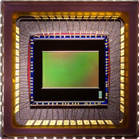
SENSOR IMAGE VGA MONO CMOS 48LCC

MT9V032C12STM

Manufacturer Part Number
MT9V032C12STM
Description
SENSOR IMAGE VGA MONO CMOS 48LCC
Manufacturer
Aptina LLC
Series
DigitalClarity®, Micron®r
Type
CMOS Imagingr
Datasheet

Specifications of MT9V032C12STM

Pixel Size
6µm x 6µm
Active Pixel Array
752H x 480V
Frames Per Second
60
Voltage - Supply
3.3V
Package / Case
48-CLCC
Lead Free Status / RoHS Status
Lead free / RoHS Compliant
Other names
557-1306
Q3986409A
Q4106028

Available stocks

Company
Part Number
Manufacturer
Quantity
Price
Part Number:
MT9V032C12STM
Manufacturer:
ATMEL
Quantity:
101
Part Number:
MT9V032C12STM-DP
Manufacturer:
ON/安森美
Quantity:
20 000
Part Number:
MT9V032C12STM-DR
Manufacturer:
ON/安森美
Quantity:
20 000
Part Number:
MT9V032C12STM-DR
0
1/3-Inch Wide-VGA CMOS Digital Image
Sensor
MT9V032C12STM (Monochrome, Pb-Free)
MT9V032C12STC (Color, Pb-Free)
Features
• Micron
• Array format: Wide-VGA, active 752H x 480V
• Global shutter photodiode pixels; simultaneous
• Monochrome or color: Near_IR enhanced
• Readout modes: Progressive or interlaced
• Shutter efficiency: >99%
• Simple two-wire serial interface
• Register lock capability
• Window size: User programmable to any smaller
• Binning: 2 x 2 and 4 x 4 of the full resolution
• ADC: On-chip, 10-bit column-parallel (option to
• Automatic controls: Auto exposure control (AEC)
• Support for four unique serial control register IDs to
• Data output formats:
Applications
PDF: 09005aef824c9998/Source: 09005aef824c999c
MT9V032_LDS_1.fm - Rev. B 3/07 EN
(360,960 pixels)
integration and readout
performance for use with non-visible NIR
illumination
format (QVGA, CIF, QCIF, and so on). Data rate can
be maintained independent of window size
operate in 12-bit to 10-bit companding mode)
and auto gain control (AGC); variable regional and
variable weight AEC/AGC
control multiple imagers on the same bus
• Single sensor mode:
• Stereo sensor mode:
• Security
• High dynamic range imaging
• Unattended surveillance
• Stereo vision
• Video as input
• Machine vision
• Automation
• Traffic camera
10-bit parallel/stand-alone
8-bit or 10-bit serial LVDS
Interspersed 8-bit serial LVDS
®
DigitalClarity
®
CMOS imaging technology
MT9V032: 1/3-Inch Wide-VGA Digital Image Sensor
1
Table 1:
Ordering Information
Table 2:
Optical format
Active imager size
Active pixels
Pixel size
Color filter array
Shutter type
Maximum data rate/
master clock
Full resolution
Frame rate
ADC resolution
Responsivity
Dynamic range
Supply voltage
Power consumption
Operating temperature –30°C to +70°C
Packaging
Output gain
Read noise
Dark current
MT9V032C12STM ES
MT9V032C12STC ES
MT9V032C12STMD ES
MT9V032C12STMH ES
MT9V032C12STCD ES
MT9V032C12STCH ES
Part Number
Micron Technology, Inc., reserves the right to change products or specifications without notice.
Parameter
Key Performance Parameters
Available Part Numbers
48-pin CLCC (mono)
48-pin CLCC (color)
Demo kit (mono)
Demo kit headboard only
(mono)
Demo kit (color)
Demo kit headboard only (color)
1/3-inch
4.51mm(H) x 2.88mm(V)
5.35mm diagonal
752H x 480V
6.0µm x 6.0µm
Monochrome or color RGB
Bayer pattern
Global shutter—TrueSNAP™
26.6 MPS/26.6 MHz
752 x 480
60 fps (at full resolution)
10-bit column-parallel
4.8 V/lux-sec (550nm)
>55dB linear;
>80
3.3V +0.3V
<320mW at maximum data
rate; 100µW standby current
48-pin CLCC
15.3 e-/LSB
25 e-PRMS at 1X
9,042 e-/pix/s at 55°C
©2006 Micron Technology, Inc. All rights reserved.
100dB in HiDy mode
Description
(
all supplies)
Value
Preliminary
Features

Related parts for MT9V032C12STM

MT9V032C12STM Summary of contents

Page 1

... Wide-VGA CMOS Digital Image Sensor MT9V032C12STM (Monochrome, Pb-Free) MT9V032C12STC (Color, Pb-Free) Features ® ® • Micron DigitalClarity CMOS imaging technology • Array format: Wide-VGA, active 752H x 480V (360,960 pixels) • Global shutter photodiode pixels; simultaneous integration and readout • Monochrome or color: Near_IR enhanced ...

Page 2

General Description The Micron Imaging MT9V032 is a 1/3-inch wide-VGA format CMOS active-pixel digital image sensor with global shutter and high dynamic range (HDR) operation. The sensor has specifically been designed to support the demanding interior and exterior unat- tended ...

Page 3

Figure 2: MT9V032 Quantum Efficiency vs. Wavelength 350 PDF: 09005aef824c9998/Source: 09005aef824c999c MT9V032_LDS_2.fm - Rev. B 3/07 EN MT9V032: 1/3-Inch Wide-VGA Digital Image Sensor 450 550 650 750 Wavelength (nm) Micron Technology, ...

Page 4

Pin Descriptions Figure 3 shows the package pinout for the MT9V032. Table 3 on page 5 provides the pin descriptions. Figure 3: 48-Pin CLCC Package Pinout Diagram LVDSGND BYPASS_CLKIN_N BYPASS_CLKIN_P SER_DATAIN_N SER_DATAIN_P LVDSGND PDF: 09005aef824c9998/Source: 09005aef824c999c MT9V032_LDS_2.fm - Rev. B ...

Page 5

Table 3: Pin Descriptions Only pins D 0 through D OUT Pin Number Symbol 29 RSVD 10 SER_DATAIN_N 11 SER_DATAIN_P 8 BYPASS_CLKIN_N 9 BYPASS_CLKIN_P 23 EXPOSURE 25 SCLK S_CTRL_ADR0 31 S_CTRL_ADR1 32 RESET# 33 STANDBY 47 SYSCLK ...

Page 6

Table 3: Pin Descriptions (continued) Only pins D 0 through D OUT Pin Number Symbol 35 VAAPIX 6 V LVDS LVDSGND 13 GND 34 GND ...

Page 7

Electrical Specifications Table 4: DC Electrical Characteristics V = 3.3V ±0.3V; T PWR A Symbol Definition V Input high voltage IH V Input low voltage IL I Input leakage current IN V Output high voltage OH V Output low voltage ...

Page 8

Table 6: LVDS Receiver DC Specifications V = 3.3V ±0.3V; T PWR A Symbol Definition V + Input differential IDTH Iin Input current Caution Stresses greater than those listed in Table 7 may cause permanent damage to the device. Table ...

Page 9

Package Dimensions Figure 5: 48-Pin CLCC Package Outline Drawing D Seating plane A 8.8 0.8 47X 4.4 TYP 1.0 ±0 48X 0.40 ±0.05 8.8 4.4 4X 0.2 5.215 5.715 11.43 Lead finish: Au plating, 0.50 microns minimum thickness ...

Page 10

Appendix A – Serial Configurations With the LVDS serial video output, the deserializer can meters from the sensor. The serial link can save on the cabling cost of 14 wires (D FRAME_VALID, PIXCLK, GND). Instead, just ...

Page 11

Configuration of Sensor for Stereoscopic Serial Output with Internal PLL In this configuration the internal PLL generates the shift-clk (x18) in phase with the system-clock. The LVDS pins SER_DATAOUT_P and SER_DATAOUT_N must be connected to a deserializer (clocked at approximately ...

Page 12

Broadcast and Individual Writes for Stereoscopic Topology In stereoscopic mode, the two sensors are required to run in lockstep. This implies that control logic in each sensor is in exactly the same state as its pair on every clock. To ...

Page 13

Revision History Rev ...

Related keywords