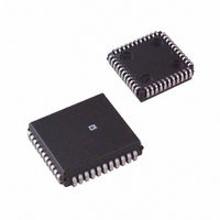
AD8600APZ Analog Devices Inc, AD8600APZ Datasheet - Page 13

AD8600APZ
Manufacturer Part Number
AD8600APZ
Description
16 CHANNEL 8-BIT MULT.DAC
Manufacturer
Analog Devices Inc
Datasheet
1.AD8600APZ-REEL.pdf
(16 pages)
Specifications of AD8600APZ
Rohs Compliant
YES
Settling Time
1µs
Number Of Bits
8
Data Interface
Parallel
Number Of Converters
16
Voltage Supply Source
Analog and Digital, Dual ±
Power Dissipation (max)
175mW
Operating Temperature
-40°C ~ 85°C
Mounting Type
Surface Mount
Package / Case
44-PLCC
Lead Free Status / RoHS Status
Lead free / RoHS Compliant
Available stocks
Company
Part Number
Manufacturer
Quantity
Price
Company:
Part Number:
AD8600APZ
Manufacturer:
Analog Devices Inc
Quantity:
10 000
Part Number:
AD8600APZ
Manufacturer:
ADI/亚德诺
Quantity:
20 000
Company:
Part Number:
AD8600APZ-REEL
Manufacturer:
Analog Devices Inc
Quantity:
10 000
REV. 0
Time Dependent Variable Gain Amplifier Using the AD600
The AD8600 is ideal for generating a control signal to set the
gain of the AD600, a wideband, low noise variable gain ampli-
fier. The AD600 (and similar parts such as the AD602 and
AD603) is often used in ultrasound applications, which require
the gain to vary with time. When a burst of ultrasound is ap-
plied, the reflections from near objects are much stronger than
from far objects. To accurately resolve the far objects, the gain
must be greater than for the near objects. Additionally, the sig-
nals take longer to reach the ultrasound sensor when reflected
from a distant object. Thus, the gain must increase as the time
increases.
The AD600 requires a dc voltage to adjust its gain over a
40 dB range. Since it is a dual, the two variable gain amplifiers
can be cascaded to achieve 80 dB of gain. The AD8600 is used
to generate a ramped output to control the gain of the AD600.
The slope of the ramp should correspond to the time delay
of the ultrasound signal. Since ultrasound applications often
require multiple channels, the AD8600 is ideal for this
application.
The circuit to achieve a time dependent variable gain amp is
shown in Figure 23. The AD600’s gain is controlled by differ-
ential inputs, C1LO and C1HI, with a gain constant of
32 dB/V. Thus for 40 dB of gain, the differential control input
*
*
*
*
loop
*
load
staa
ldx
ldaa
staa
ldab
ldaa
staa
inca
staa
cba
bne
jmp
ddrc
#$00
0,x
portb
#$ff
#$00
portc
portc
load
loop
Figure 22. 68HC11 Microcode to Interface to the AD8600.
set x to point to the DAC address
load the address from 68HC11 mem
set the address on portb
LD, CS, EN, R/W are all low for
transparent DAC loading
set accumulator b to 255
start the triangle wave at zero
write the data to the AD8600
increase the data by one
send the new data to the AD8600
compare a to b
we haven’t reached 255 yet
we have reached 255, so start over
–13–
needs to be 1.25 V. In this application, the C1LO input is set at
the midscale voltage of 0.625 V, which is generated by a simple
voltage divider from the REF43. The AD8600’s output is di-
vided in half, generating a 0 V to 1.25 V ramp, and then applied
to C1HI. This ramp sweeps the gain from 0 dB to 40 dB.
Figure 23. Ultrasound Amplifier with Digitally Controlled
Variable Gain
DIGITAL
CONTROL
4
REF43
+5V
2
V
CC
AD8600
+2.5V
6
, V
V
DD1
2
+5V
REF
, V
DD2
ULTRASOUND
SENSOR)
(FROM
O
13
V
ø
IN
10k
R1
10k
R2
A1LO
A1HI
30k
R3
GAT1
2
3
4
C1
100pF
0V – 1.25V
C1LO
1
C1HI
16
0.625V
R4
10k
AD600
–5V
+5V
AD8600
V
13
12
POS
15
A1CM
A1OP
14
V
OUT


