AD7891ASZ-2 Analog Devices Inc, AD7891ASZ-2 Datasheet - Page 10
AD7891ASZ-2
Manufacturer Part Number
AD7891ASZ-2
Description
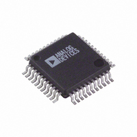
IC,Data Acquisition System,8-CHANNEL,12-BIT,QFP,44PIN,PLASTIC
Manufacturer
Analog Devices Inc
Type
Data Acquisition System (DAS)r
Datasheet
1.AD7891BSZ-2.pdf
(20 pages)
Specifications of AD7891ASZ-2
Resolution (bits)
12 b
Sampling Rate (per Second)
500k
Data Interface
Serial, Parallel
Voltage Supply Source
Single Supply
Voltage - Supply
5V
Operating Temperature
-40°C ~ 85°C
Mounting Type
Surface Mount
Package / Case
44-MQFP, 44-PQFP
Number Of Elements
1
Resolution
12Bit
Sample Rate
500KSPS
Input Polarity
Unipolar/Bipolar
Input Type
Voltage
Rated Input Volt
2.5/5/±2.5V
Differential Input
No
Power Supply Requirement
Single
Single Supply Voltage (typ)
5V
Single Supply Voltage (min)
4.75V
Single Supply Voltage (max)
5.25V
Dual Supply Voltage (typ)
Not RequiredV
Dual Supply Voltage (min)
Not RequiredV
Dual Supply Voltage (max)
Not RequiredV
Power Dissipation
100mW
Differential Linearity Error
±1LSB
Integral Nonlinearity Error
±1LSB
Operating Temp Range
-40C to 85C
Operating Temperature Classification
Industrial
Mounting
Surface Mount
Pin Count
44
Package Type
MQFP
Input Signal Type
Single-Ended
Lead Free Status / RoHS Status
Lead free / RoHS Compliant
Lead Free Status / RoHS Status
Lead free / RoHS Compliant
Available stocks
Company
Part Number
Manufacturer
Quantity
Price
Company:

Part Number:
AD7891ASZ-2
Manufacturer:
Analog Devices Inc
Quantity:
10 000
Part Number:
AD7891ASZ-2
Manufacturer:
ADI/亚德诺
Quantity:
20 000
Company:
Part Number:
AD7891ASZ-2REEL
Manufacturer:
Analog Devices Inc
Quantity:
10 000


AD7891
CONVERTER DETAILS
The AD7891 is an 8-channel, high speed, 12-bit data acquisi-
tion system. It provides the user with signal scaling, multiplexer,
track/hold, reference, ADC, and high speed parallel and serial
interface logic functions on a single chip. The signal condition-
ing on the AD7891-1 allows the part to accept analog input
ranges of ± 5 V or ± 10 V when operating from a single supply.
The input circuitry on the AD7891-2 allows the part to handle
input signal ranges of 0 V to +2.5 V, 0 V to +5 V, and ±2.5 V
again while operating from a single 5 V supply. The part requires
a 2.5 V reference that can be provided from the part’s own internal
reference or from an external reference source.
Conversion is initiated on the AD7891 either by pulsing the
CONVST input or by writing a Logic 1 to the SWCONV bit of
the control register. When using the hardware CONVST input,
the on-chip track/hold goes from track to hold mode and the
conversion sequence is started on the rising edge of the CONVST
signal. When a software conversion start is initiated, an internal
pulse is generated, delaying the track/hold acquisition point and
the conversion start sequence until the pulse is timed out. This
internal pulse is initiated (goes from low to high) whenever a
write to the AD7891 control register takes place with a 1 in the
SWCONV bit. It then starts to discharge and the track/hold
cannot go into hold and conversion cannot be initiated until the
pulse signal goes low. The internal pulse duration is equal to the
track/hold acquisition time. This allows the user to obtain a
valid result after changing channels and initiating a conversion
in the same write operation.
The conversion clock for the part is internally generated and
conversion time for the AD7891 is 1.6 ms from the rising edge of
the hardware CONVST signal. The track/hold acquisition time
for the AD7891-1 is 600 ns, while the track/hold acquisition
time for the AD7891-2 is 400 ns. To obtain optimum perfor-
mance from the part, the data read operation should not occur
during the conversion or during the 100 ns prior to the next
conversion. This allows the AD7891-1 to operate at throughput
rates up to 454.5 kSPS and the AD7891-2 to operate at through-
put rates up to 500 kSPS in the parallel mode and achieve data
sheet specifications. In the serial mode, the maximum achievable
throughput rate for both the AD7891-1 and the AD7891-2 is
357 kSPS (assuming a 20 MHz serial clock).
All unused analog inputs should be tied to a voltage within the
nominal analog input range to avoid noise pickup. For mini-
mum power consumption, the unused analog inputs should be
tied to AGND.
–10–
INTERFACE INFORMATION
The AD7891 provides two interface options, a 12-bit parallel
interface and a high speed serial interface. The required inter-
face mode is selected via the MODE pin. The two interface
modes are discussed in the following sections.
Parallel Interface Mode
The parallel interface mode is selected by tying the MODE
input to a logic high. Figure 2 shows a timing diagram illustrating
the operational sequence of the AD7891 in parallel mode for a
hardware conversion start. The multiplexer address is written to
the AD7891 on the rising edge of the WR input. The on-chip
track/hold goes into hold mode on the rising edge of CONVST;
conversion is also initiated at this point. When the conversion is
complete, the end of conversion line (EOC) pulses low to indi-
cate that new data is available in the AD7891’s output register.
This EOC line can be used to drive an edge-triggered interrupt
of a microprocessor. CS and RD going low accesses the 12-bit
conversion result. In systems where the part is interfaced to a
gate array or ASIC, this EOC pulse can be applied to the CS
and RD inputs to latch data out of the AD7891 and into the
gate array or ASIC. This means the gate array or ASIC does not
need any conversion status recognition logic, and it also elimi-
nates the logic required in the gate array or ASIC to generate
the read signal for the AD7891.
DB0 TO DB11
CONVST (I)
EOC (O)
CS (O)
WR (I)
RD (I)
(I/O)
t
Figure 2. Parallel Mode Timing Diagram
NOTE
I = INPUT
O = OUTPUT
1
VALID DATA
t
INPUT
2
t
3
t
5
t
4
t
6
t
CONV
t
7
t
1
t
9
t
VALID DATA
8
OUTPUT
REV. D
t
5
t
10
Related parts for AD7891ASZ-2
Image
Part Number
Description
Manufacturer
Datasheet
Request
R

Part Number:
Description:
RF/COAXIAL ADAPTER, TRB JACK-TRB JACK
Manufacturer:
TROMPETER ELECTRONICS
Datasheet:

Part Number:
Description:
±1.7g Dual-Axis IMEMS Accelerometer Evaluation Board
Manufacturer:
Analog Devices Inc
Datasheet:

Part Number:
Description:
Inertial Sensor Evaluation System
Manufacturer:
Analog Devices Inc
Datasheet:
Part Number:
Description:
Manufacturer:
Analog Devices Inc
Datasheet:
Part Number:
Description:
Manufacturer:
Analog Devices Inc
Datasheet:
Part Number:
Description:
Manufacturer:
Analog Devices Inc
Datasheet:
Part Number:
Description:
Manufacturer:
Analog Devices Inc
Datasheet:
Part Number:
Description:
Manufacturer:
Analog Devices Inc
Datasheet:
Part Number:
Description:
Manufacturer:
Analog Devices Inc
Datasheet:
Part Number:
Description:
Manufacturer:
Analog Devices Inc
Datasheet:
Part Number:
Description:
Manufacturer:
Analog Devices Inc
Datasheet:
Part Number:
Description:
Manufacturer:
Analog Devices Inc
Datasheet:
Part Number:
Description:
Manufacturer:
Analog Devices Inc
Datasheet: