DFLZ10-7 Diodes Inc, DFLZ10-7 Datasheet
DFLZ10-7
Specifications of DFLZ10-7
Available stocks


Related parts for DFLZ10-7


DFLZ10-7 Summary of contents
Page 1
... Thermal Resistance Junction to Soldering Point (Note 3) Operating and Storage Temperature Range Notes: 1. Device mounted on 1" x 1", FR-4 PCB; 2 oz. Cu pad layout as shown on Diodes Inc. suggested pad layout document AP02001.pdf Directive 2002/95/EC (RoHS). All applicable RoHS exemptions applied, see EU Directive 2002/95/EC Annex Notes. 3. Theoretical R calculated from the top center of the die straight down to the PCB/cathode tab solder junction. θ ...
Page 2
... FHL 5.6 5.2 DFLZ6V2 FHN 6.2 5.8 DFLZ6V8 FHO 6.8 6.4 DFLZ7V5 FHQ 7.5 7.0 DFLZ8V2 FHR 8.2 7.7 DFLZ9V1 FHT 9.1 8.5 DFLZ10 FHU 10 9.4 DFLZ11 FHV 11 10.4 DFLZ12 FHW 12 11.4 DFLZ13 FHX 13 12.4 DFLZ15 FHZ 15 13.8 DFLZ16 FJA 16 15.3 ...
Page 3
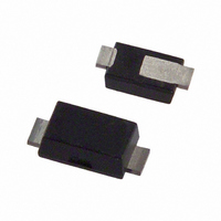
... Code R S Month Jan Feb Code 1 2 Package Outline Dimensions PowerDI is a registered trademark of Diodes Incorporated. DFLZ5V1 - DFLZ39 Document number: DS30464 Rev 1MHz T = 25°C A 100 Packaging ® PowerDI 123 Fxx = Product Type Marking Code (See Electrical Characteristics Table) Fxx YM = Date Code Marking ...
Page 4
... Diodes Incorporated and its subsidiaries reserve the right to make modifications, enhancements, improvements, corrections or other changes without further notice to any product herein. Diodes Incorporated does not assume any liability arising out of the application or use of any product described herein; neither does it convey any license under its patent rights, nor the rights of others. The user of products in such applications shall assume all risks of such use and will agree to hold Diodes Incorporated and all the companies whose products are represented on our website, harmless against all damages ...