Introduction
The HV823DB1 EL Driver demo board contains all the circuitry
necessary to drive an EL (Electroluminescent) lamp. Simply
connect it to a power supply and a lamp as shown below.
The supplied circuit has been optimized to drive an 8in
component values to suit a particular application. To assist in customization, various circuits optimized for a variety of applications are
provided. For additional assitance in designing EL driver circuits, please refer to Application Notes AN-H33 ( EL Lamp Driver Circuits ) and
AN-H34 ( HV823 & HV825 EL Lamp Driver Circuits) .
07/13/00
Supertex Inc. does not recommend the use of its products in life support applications and will not knowingly sell its products for use in such applications unless it receives an adequate "products liability
indemnification insurance agreement." Supertex does not assume responsibility for use of devices described and limits its liability to the replacement of devices determined to be defective due to
workmanship. No responsibility is assumed for possible omissions or inaccuracies. Circuitry and specifications are subject to change without notice. For the latest product specifications, refer to the
Supertex website: http://www.supertex.com. For complete liability information on all Supertex products, refer to the most current databook or to the Legal/Disclaimer page on the Supertex website.
EN
Enables/disables the lamp driver. A logic high (V
driver and a logic low (GND) disables the driver. This input may
be connected to a mechanical switch as shown, or to a logic circuit
output that has a source impedance of less than 20k .
V
Supplies the HV823 EL driver IC. The supplied circuit is optimized
for 3.0V to 3.3V operation. Current draw is typically 100 A when
enabled and less than 1 A when disabled.
DD
Enable Input
IC Supply
Enable
On
Off
3.0–3.3V
connect together
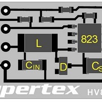
Board Layout & Connections
DD
V
GND
EN
V
) enables the
DD
IN
2
lamp from a 3.0V to 3.3V supply. The circuit may be customized with different
C
DD
C
IN
L
R
SW
1
D
R
EL
Specifications
Supply Voltage
Supply Current
Lamp Size Range
Lamp Frequency
Converter Frequency
V
Supplies the high voltage power converter. Current draw is
approximately 50mA.
GND
Connect to V
both V
supply bypass capacitor is not necessary.
V
Connect to EL lamp of 3 to 12 square inches. Polarity is irrelevant.
IN
A
823
HV823DB1
and V
C
C
DD
S
SW
Inductor Supply
and V
Circuit Ground
V
V
B
EL Driver Demo Board
A
DD
B
IN
negative terminal. Supply bypass capacitors for
Lamp Connections
are provided on the demo board. An external
HV823DB1
3 to 12 in
EL Lamp
3.0 - 3.3V
~260Hz
~50kHz
~50mA
2