K3010PG Vishay, K3010PG Datasheet - Page 3
K3010PG
Manufacturer Part Number
K3010PG
Description
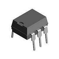
Triac & SCR Output Optocouplers Phototriac Output Non-Zero Crossing
Manufacturer
Vishay
Specifications of K3010PG
Isolation Voltage
1.6 KV
Configuration
1
Maximum Continuous Output Current
100 mA
Maximum Input Current
80 mA
Maximum Operating Temperature
+ 85 C
Maximum Power Dissipation
350 mW
Maximum Reverse Diode Voltage
5 V
Minimum Operating Temperature
- 40 C
Output Type
AC
Package / Case
DIP-6
Typical Input Voltage
1.25 V
Zero-crossing Circuit
No
Output Device
PhotoTriac
Peak Output Voltage (vdrm)
250 V
Maximum Input Voltage
1.6 V
Maximum Output Voltage
175 VAC
Minimum Trigger Current
8 mA (Typ)
No. Of Channels
1
Optocoupler Output Type
Phototriac
Input Current
50mA
Output Voltage
250V
Opto Case Style
DIP
No. Of Pins
6
Mounting Type
Through Hole
Lead Free Status / RoHS Status
Lead free / RoHS Compliant


Note
(1)
(2)
(3)
Document Number: 83504
Rev. 1.8, 28-Nov-07
ELECTRICAL CHARACTERISTICS
PARAMETER
INPUT
Forward voltage
Junction capacitance
OUTPUT
Forward peak off-state voltage
(repetitive)
Peak on-state voltage
Critical rate of rise of off-state voltage
COUPLER
Collector emitter saturation voltage
Holding current
T
Minimum and maximum values are testing requirements. Typical values are characteristics of the device and are the result of engineering
evaluation. Typical values are for information only and are not part of the testing requirements.
Test voltage must be applied within dV/dt ratings.
I
FT
amb
is defined as a minimum trigger current.
= 25 °C, unless otherwise specified.
(3)
For technical questions, contact: optocoupler.answers@vishay.com
R
I
FT
S
V
I
I
TEST CONDITION
F
FT
S
Optocoupler, Phototriac Output,
V
= 10 mA, V
R
= 3 V, R
I
I
= 0, I
RDM
TM
Fig. 1 - Test Circuit for dV/dt
I
= 0, f = 1 MHz
F
= 50 mA
= 100 mA
(1)
= 100 nA
FT
= 30 mA,
L
= 150 Ω
S
≥ 3 V
250 V V
95 10813
K3010PG
K3011PG
K3012PG
K3010P
K3011P
K3012P
DRM
PART
cr
and dV/dt
R
L
SYMBOL
V
dV/d
dV/d
DRM
K3010P/K3010PG Series
crq
V
V
I
I
I
I
I
I
C
I
FT
FT
FT
FT
FT
FT
TM
H
V~
F
j
tcrq
tcr
(2)
Vishay Semiconductors
MIN.
250
0.1
Test condition:
dV/dt
V
(Sine wave)
R
dV/dt
V
(Sine wave)
R
S
eff
L
L
= 33 k
= 2 k
= 2/3 V
= 30 V
cr
crq
TYP.
1.25
100
1.5
0.2
50
10
8
8
5
5
2
2
DRM
MAX.
1.6
15
15
10
10
3
5
5
www.vishay.com
UNIT
mA
mA
mA
mA
mA
mA
pF
nA
nA
µA
V
V
V
3
Related parts for K3010PG
Image
Part Number
Description
Manufacturer
Datasheet
Request
R

Part Number:
Description:
357-036-542-201 CARDEDGE 36POS DL .156 BLK LOPRO
Manufacturer:
Vishay
Datasheet:
Part Number:
Description:
357-036-542-201 CARDEDGE 36POS DL .156 BLK LOPRO
Manufacturer:
Vishay
Datasheet:
Part Number:
Description:
357-036-542-201 CARDEDGE 36POS DL .156 BLK LOPRO
Manufacturer:
Vishay
Datasheet:
Part Number:
Description:
357-036-542-201 CARDEDGE 36POS DL .156 BLK LOPRO
Manufacturer:
Vishay
Datasheet:
Part Number:
Description:
357-036-542-201 CARDEDGE 36POS DL .156 BLK LOPRO
Manufacturer:
Vishay
Datasheet:
Part Number:
Description:
357-036-542-201 CARDEDGE 36POS DL .156 BLK LOPRO
Manufacturer:
Vishay
Datasheet:
Part Number:
Description:
357-036-542-201 CARDEDGE 36POS DL .156 BLK LOPRO
Manufacturer:
Vishay
Datasheet:
Part Number:
Description:
357-036-542-201 CARDEDGE 36POS DL .156 BLK LOPRO
Manufacturer:
Vishay
Datasheet:
Part Number:
Description:
357-036-542-201 CARDEDGE 36POS DL .156 BLK LOPRO
Manufacturer:
Vishay
Datasheet:
Part Number:
Description:
357-036-542-201 CARDEDGE 36POS DL .156 BLK LOPRO
Manufacturer:
Vishay
Datasheet:
Part Number:
Description:
357-036-542-201 CARDEDGE 36POS DL .156 BLK LOPRO
Manufacturer:
Vishay
Datasheet:
Part Number:
Description:
357-036-542-201 CARDEDGE 36POS DL .156 BLK LOPRO
Manufacturer:
Vishay
Datasheet:
Part Number:
Description:
357-036-542-201 CARDEDGE 36POS DL .156 BLK LOPRO
Manufacturer:
Vishay
Datasheet:
Part Number:
Description:
357-036-542-201 CARDEDGE 36POS DL .156 BLK LOPRO
Manufacturer:
Vishay
Datasheet:
Part Number:
Description:
357-036-542-201 CARDEDGE 36POS DL .156 BLK LOPRO
Manufacturer:
Vishay
Datasheet: