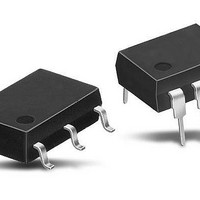
AQW214E Panasonic, AQW214E Datasheet - Page 3

AQW214E
Manufacturer Part Number
AQW214E
Description
Solid State Relays 100MA 400V DPST
Manufacturer
Panasonic
Datasheet
1.AQW210HLA.pdf
(3 pages)
Specifications of AQW214E
Control Voltage Range
1.5 V to 5 V
Load Voltage Rating
400 V
Load Current Rating
100 mA
Contact Form
2 Form A
Output Device
MOSFET
Mounting Style
Through Hole
Relay Type
PhotoMOS
Turn-on Switching
Instantaneous
Package / Case
DIP-8
Termination Style
Solder Pin
Lead Free Status / RoHS Status
Lead free / RoHS Compliant
Available stocks
Company
Part Number
Manufacturer
Quantity
Price
Company:
Part Number:
AQW214E
Manufacturer:
Panasonic Electric Works
Quantity:
1 808
Company:
Part Number:
AQW214E
Manufacturer:
SIPEX
Quantity:
5 510
Company:
Part Number:
AQW214EA
Manufacturer:
NAIS
Quantity:
5 510
Company:
Part Number:
AQW214EA
Manufacturer:
PHILIPS
Quantity:
5 510
Company:
Part Number:
AQW214EH
Manufacturer:
ЛЙПВ
Quantity:
1 000
Part Number:
AQW214EH
Manufacturer:
NAIS
Quantity:
20 000
Part Number:
AQW214EHA
Manufacturer:
PANASONIC/松下
Quantity:
20 000
Part Number:
AQW214EHAX
Manufacturer:
PANASONIC/松下
Quantity:
20 000
GU 2 Form A Current Limiting (AQW210HL)
4. Turn off time vs. ambient temperature
characteristics
LED current: 5 mA; Load voltage: Max.(DC);
Continuous load current: Max.(DC)
7. LED dropout voltage vs. ambient
temperature characteristics
LED current: 5 to 50 mA
10. Turn on time vs. LED forward current
characteristics
Measured portion: between terminals 5 and 6, 7 and 8;
Load voltage: Max.(DC); Continuous load current:
Max.(DC); Ambient temperature: 25°C
What is current limit
When a load current reaches the
specified output control current, a current
limit function works against the load
current to keep the current a constant
value.
The current limit circuit built into the
PhotoMOS relay thus controls the
instantaneous load current to effectively
ensure circuit safety.
1.5
1.4
1.3
1.2
1.1
1.0
0.25
0.15
0.05
2.5
1.5
0.5
0
0.3
0.2
0.1
3
2
1
0
–40 –20
0
–40
10
–20
0
Ambient temperature, °C
20
LED forward current, mA
Ambient temperature, °C
0
20
30
20
40
40
40
60
77°F
60
50
80 85
50mA
30mA
20mA
10mA
5mA
80 85
60
All Rights Reserved © COPYRIGHT Panasonic Electric Works Co., Ltd.
5. LED operate current vs. ambient
temperature characteristics
Load voltage: Max.(DC);
Continuous load current: Max.(DC)
8. Current vs. voltage characteristics of output
at MOS portion
Measured portion: between terminals 5 and 6, 7 and 8;
Ambient temperature: 25°C
11. Turn off time vs. LED forward current
characteristics
Measured portion: between terminals 5 and 6, 7 and 8;
Load voltage: Max.(DC); Continuous load current:
Max.(DC); Ambient temperature: 25°C
This safety feature protects circuits
downstream of the PhotoMOS relay
against over-current.
But, if the current-limiting feature is used
longer than the specified time, the
PhotoMOS relay can be destroyed.
Therefore, set the output loss to the max.
rate or less.
• Comparison of output voltage and
output current characteristics
0.15
0.05
–5
0.2
0.1
5
4
3
2
1
0
0
–4
0
–40
–3
10
–20
–2
–1
20
Ambient temperature, °C
140
120
100
0
80
60
40
20
LED forward current, mA
–20
–40
–60
–80
–100
–120
–140
77°F
20
30
1
40
Voltage, V
2
40
3
60
77°F
4
50
80 85
5
60
6. LED turn off current vs. ambient temperature
characteristics
Load voltage: Max.(DC);
Continuous load current: Max.(DC)
9. Off state leakage current vs. load voltage
characteristics
Measured portion: between terminals 5 and 6, 7 and 8;
Ambient temperature: 25°C
12. Output capacitance vs. applied voltage
characteristics
Measured portion: between terminals 5 and 6, 7 and 8;
Frequency: 1 MHz; Ambient temperature: 25°C
V-I Characteristics
10
10
10
10
50
40
30
20
10
–3
–6
–9
–12
5
4
3
2
1
0
0
0
0
–40
20
10
–20
Output voltage
Ambient temperature, °C
0
40
20
Applied voltage, V
Load voltage, V
77°F
20
60
30
40
60
80
40
80 85
100
50
77°F


