200277-4 TE Connectivity, 200277-4 Datasheet - Page 8
200277-4
Manufacturer Part Number
200277-4
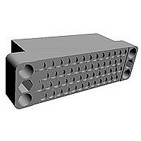
Description
RECTANGULAR HOUSING, RECEPTACLE, 50WAY
Manufacturer
TE Connectivity
Type
Housingr
Series
Mr
Specifications of 200277-4
Number Of Contacts
50POS
Number Of Contact Rows
4
Body Orientation
Straight
Pitch (mm)
3.81mm
Gender
RCP
Housing Material
Diallyl Phthalate
Operating Temp Range
-65C to 125C
Housing Color
Blue
Product Height (mm)
19.05mm
Product Depth (mm)
23.24mm
No. Of Contacts
50
No. Of Rows
4
Pitch Spacing
3.81mm
Contact Gender
Socket
Connector Mounting
Cable
Connector Type
Rectangular Power
Rohs Compliant
Yes
Angle
Straight
Brand/series
M Series
Color
Blue
Color, Housing
Blue
Length, Overall
2.593 "
Material, Housing
Diallyl-Phthalate
Mounting Hole Size
0.13 "
Mounting Type
Free Hanging, Panel Mount
Number Of Positions
50
Number Of Rows
4
Pin Spacing
0.15 "
Primary Type
Interconnect System
Special Features
Free Hanging
Standards
RoHS Compliant, ELV Compliant
Product Type
Housing
Type Of Connector
Standard
Mount
Free Hanging, Panel
Mounting Hardware
None
Center Fastener
No
Connector Style
Receptacle
Rohs/elv Compliance
RoHS compliant, ELV compliant
Lead Free Solder Processes
Wave solder capable to 240°C, Wave solder capable to 260°C, Wave solder capable to 265°C
Rohs/elv Compliance History
Always was RoHS compliant
Packaging Method
Loose Piece
Lead Free Status / RoHS Status
Compliant


8
The presentation of current- car-
rying capacity in AMP product
specifications includes two parts:
First, a base curve showing cur-
Next are rating factors; a table
Practical Values
The current-rating method gives
designers practical values appli-
cable to their applications. While
the specified current levels for a
contact may be lower than for
other testing methods, they are
more realistic and simplify the
system design process.
“Spec-manship” is replaced
by a realistic assessment of the
current-carrying capacity of a
Connector/Contact
Acceptability
As previously stated, choosing the
appropriate connector/contact
combination is fundamental to the
successful function of all connec-
tors. The Selection Chart, shown at
right, is designed to simplify your
choice of connectors and their
acceptable contacts. Once you
have selected the wire size, cur-
rent-carrying capacity need,
number of positions required, and
the type of contacts needed in
your choice of connector, refer to
this matrix for a quick look at
exactly what is acceptable in a
given connector type.
Catalog 82003
Revised 06-08
www.tycoelectronics.com
rent levels versus T-rise for a
single circuit and the largest wire
size (See figure 1). This repre-
sents the maximum current
capacity of the contact. The
curve is usually flat up to 75°C
ambient and then drops off. Up
to 75°C, the 30°C T-rise limits
the amount of current, and
above 75°C the current must be
reduced to keep the combina-
tion of ambient temperature
and T-rise from exceeding the
maximum operating tempera-
ture of 105°C.
of multipliers to account for
connector loading and for
smaller wire sizes (See figure 2).
The designer first determines
the base current for the ambi-
ent conditions of the
application; then multiplies this
base current by the rating fac-
tors to find the current level for
the application’s loading factor
and wire size.
Dimensions are in millimeters
and inches unless otherwise
specified. Values in brackets are
equivalent U.S. Customary Units.
AMP M Series
Pin and Socket Connectors
Presentation - Example of New Current Rating Format
Note: Data is not typical of a spe-
cific M Series connector
configuration. For specific
current rating information based
on % connector loading, contact
Tyco Electronics.
To demonstrate the method of
specifying current, consider the
following application conditions;
an ambient temperature of 65°C, a
50% loading of contacts in the
housing, and 20 AWG [0.6mm 2 ]
wire.
From Figure 1, the base current
Figure 2, the rating factor for
The specific rating for this appli-
Each of the contacts can carry
However, if the ambient tem-
contact under varying conditions
of temperature, connector load-
ing, and wire size.
Specific current-carrying data
based on EOL and % loading
is available from Tyco Electronics
Corporation. Please contact your
local Sales Engineer or call Tyco
Electronics Corporation.
Contact Selection Chart
M Series
M Series
Special
Connector
rating is 14 ampere with 18 AWG
[0.8mm 2 ] wire.
50% loading and 20 AWG
[0.6mm 2 ] wire is 0.68.
cation is the product of the
base rating and the rating factor:
9.5 ampere.
perature is 80°C the allowable
T-rise becomes 25°C. The base
current must be lowered to 12.8
ampere so that the 105°C maxi-
mum operating temperature is
not exceeded. The current rat-
ing then becomes:
Type
12.8 x 0.68 = 8.7 ampere.
14 x 0.68 = 9.5 ampere
Type I
Type II
Dimensions are shown for
reference purposes only.
Specifications subject
to change.
High Current
Type II/III
Graph shows the relationship between base current, ambient
temperature, and contact T-rise.
0
Rating factors allow the base current to be adjusted for various
connector loading and wire sizes.
Type III+
10
Single
100%
30%
50%
70%
USA: 1-800-522-6752
Canada: 1-905-470-4425
Mexico: 01-800-733-8926
C. America: 52-55-5-729-0425
20
Type III+
Posted
NOTE: All part numbers
are RoHS Compliant
30
.97
.83
.65
.55
18
1
Type XII
Ambient Temperature (C)
40
.83
.80
.68
.53
.45
20
50
High Current
Type XII
Figure 2
60
AWG
.69
.66
.57
.45
.38
22
70
South America: 55-11-3611-1514
Hong Kong: 852-2735-1628
Japan: 81-44-844-8013
UK: 44-141-810-8967
Mini-coax
80
.59
.57
.48
.38
.32
24
Single Contact
90
Sub-Mini
18 AWG
Coax
.50
.49
.42
.33
.28
26
100
15
10
5
0
Related parts for 200277-4
Image
Part Number
Description
Manufacturer
Datasheet
Request
R

Part Number:
Description:
RECTANGULAR HOUSING, RECEPTACLE, 50WAY
Manufacturer:
TE Connectivity
Datasheet:

Part Number:
Description:
Printers THERMAL PRINTER HS-SLEEVE MARKER
Manufacturer:
TE Connectivity


Part Number:
Description:
High Speed / Modular Connectors 30P HEADER ASSY
Manufacturer:
TE Connectivity
Datasheet:

Part Number:
Description:
High Speed / Modular Connectors REC 6X005P R/A LT B-PLANE HS3
Manufacturer:
TE Connectivity
Datasheet:

Part Number:
Description:
High Speed / Modular Connectors 2MM HM RCPT 50P R/A AU
Manufacturer:
TE Connectivity
Datasheet:

Part Number:
Description:
High Speed / Modular Connectors 2MM HM RCPT 50P R/A AU
Manufacturer:
TE Connectivity
Datasheet:


Part Number:
Description:
Manufacturer:
TE Connectivity
Datasheet:


Part Number:
Description:
Manufacturer:
TE Connectivity
Datasheet:

Part Number:
Description:
Manufacturer:
TE Connectivity
Datasheet:

Part Number:
Description:
Manufacturer:
TE Connectivity
Datasheet: